


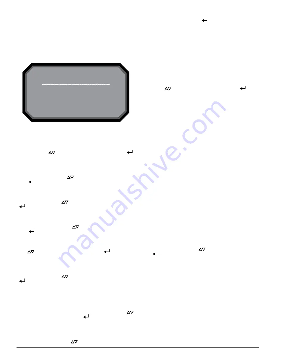
Enter Password
* * 4 _
ASP123-00
FIGURE 13. FUNCTIONS MENU SCREEN
3. FUNCTIONS
The Functions menu screen is used to change the device’s state or activate
test mode. Because this menu allows the user to change the device out of
its normal operating state there is an optional lockout feature for this menu.
The lockout requires a 4-digit passcode to enter the functions menu – this
pass¬code is set using the PipeIQ Software. When the functions menu has
been accessed from the main menu screen with the lock feature enabled, the
enter password screen will appear.
From the functions menu the following options are available:
3.1. ISOLATE
The Isolate function will set the device into the isolate mode. When this func-
tion is selected from the functions menu the device will ask for a confirma-
tion. Use the scroll (
) keys to select cancel or ok and then select (
)
key to confirm the selection.
3.2. DISABLE
The Disable function will set the device into the Disable mode. When
this function is selected from the functions menu the device will ask for
confirma¬tion. Use the scroll (
) keys to select cancel or ok and then
select (
) key to confirm the selection.
3.3. RESET BASELINE
The Reset Baseline function will set the device into the Reset Baseline mode.
When this function is selected from the functions menu the device will ask for
confirmation. Use the scroll (
) keys to select cancel or ok and then select
(
) key to confirm the selection.
3.4. RESET IP
The Reset IP Network function will set the device into the Reset IP Network
mode. When this function is selected from the functions menu the device will
ask for confirmation. Use the scroll (
) keys to select cancel or ok and then
select (
) key to confirm the selection.
3.5. TEST MODE
The Test function will set the device into the Test mode. When this function is
selected from the functions menu the device will ask for confirmation. Use the
scroll (
) keys to select cancel or ok and then select (
) key to confirm
the selection.
3.6. SOUNDER TEST
The Sounder Test function will set the device into the Sounder Test mode.
When this function is selected from the functions menu the device will ask for
confirmation. Use the scroll (
) keys to select cancel or ok and then select
(
) key to confirm the selection.
After confirmation the tones will be exercised on the sounder. Since the
sounder is configurable the screen will display which tone it is currently
giv¬ing (fault or alarm).
3.7. RESET
The Reset function will reset the device. When this function is selected from
the functions menu the device will ask for confirmation. Use the scroll (
)
keys to select cancel or ok and then select (
) key to confirm the selection.
3.8. SET TIME
The Set Time screen allows the user to set the time and date of the device.
This feature can be locked out and require the user to enter a 4 digit access
code to enter the set time menu. When first entering the screen the hour time
will be highlighted. Use the scroll (
) keys to change the value. When the
8 ASUG80001
desired hour is selected use the select (
) key to set the hour and the cur-
sor will advance to the minutes. As each field is set the cursor will progress
until it reaches the end. After all fields have been entered, the device will ask
for a confirmation.
4. CONFIGURATION
The Configuration menu provides access to view how the device is
specifi¬cally configured from PipeIQ. Because this menu contains potentially
sensitive information, such as email addresses, there is an optional lockout
feature on this menu. The lockout requires a user to enter a 4 digit access
code to enter the Functions menu. This four digit access code is configurable
through Pi¬peIQ. When a user selects the Functions menu from the main
menu screen with the lock feature enabled, the enter password screen will be
displayed. All configuration data is read only. From the main configuration
menu the follow¬ing selections are available:
Use the scroll (
) keys to select an option and then select (
) key to
confirm the selection.
4.1. GENERAL SETTINGS
The General Settings screen provides the miscellaneous settings that are con-
figured. The following configuration settings can be seen under the general
settings:
• 4.1.1. Fan speed
• 4.1.2. Flow Boundary
• 4.1.3. Airflow Delay
• 4.1.4. Trend period
• 4.1.5. Address
• 4.1.6. Alarm Tone
• 4.1.7. Fault Tone
• 4.1.8. Acclimate
4.2. NETWORK
The Network screen provides the MAC address of the device and the TCP/IP
network settings in the device.
• 4.2.1. MAC
• 4.2.2. IP Address
• 4.2.3. Subnet Mask
• 4.2.4. Gateway
• 4.2.5. DNS primary
• 4.2.6. DNS Secondary
• 4.2.7. DHCP Status
• 4.2.8. Device Name
• 4.3. Email
The Email menu screen provides the options for a detailed look of the email
settings in the device. Use the scroll (
) keys to select an option and then
select (
) key to confirm the selection.
• 4.3.1. Device Account
• 4.3.2. Addresses
• 4.4. Modbus
• 4.4.1 Mode
• 4.4.2. IP Address
• 4.4.3. Port
• 4.4.4. Address
• 4.5. Alarm Settings
• 4.5.1. Alarm Threshold
• 4.5.2. Night Mode
• 4.5.3. DST Setting
• 4.5.4. Alarm Delays
• 4.5.5. Relay Settings
• 4.5.6. Information