background image

6

a

ENGLISH

Close the gate leaf and install the front fitting on the rod as 
shown in Fig. 11 re. 

b

.

Establish  the  fixing  position  of  the  front  fitting  on  the  leaf 
and mark the fixing points (Fig. 12) 

(the operator must be 

perfectly level).

Disassemble  the  operator  from  the  front  fixing  to  avoid 
damaging the rod when the front fixing is installed on the 
gate.
Weld the front fixing directly on the leaf or screw it by means 
of threaded inserts.
If an opening mechanical stop on ground is not installed, 
spacers  can  be  used  (Fig.  1  re. 

g

).  Remove  the  front 

articulated joint and insert on the rod the number of spacers 
required to reach the desired opening angle (Fig. 14).

10.

11.

12.

13.

14.

If  an  external  mechanical 
stop

  point  at  closure  is  pre-

sent, remove the rod comple-
tely and then insert it 5 mm.

Fig. 12

Fig. 13

Fig. 15

Fig. 16

 MINIMUM 

BENDING

RADIUS

60 mm

 MINIMUM 

BENDING

RADIUS

60 mm

Fig. 17

Fig. 14

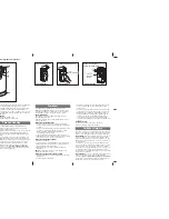
Secure the operator to the front fixing (Fig. 15).
Remove  the  bleed  screw  (Fig.16  ref. 

a

)  paying  special  

attention to leave the sealing O-Ring in its seat
Install the metallic protection cover as shown in Fig. 16, insert 
and tighten both tie-rods
Connect the cable to the operator using the two screws 
supplied, as shown in Fig. 17.

15.
16.

17.

18.

www.metalines.com

[email protected]

Summary of Contents for S450 UK KIT-CBAC

Page 1: ...S450H www metalines com sales metalines com...

Page 2: ...12978 protect from the hazards caused by mechanical movements such as crushing entrapment and shearing hazards 17 Each installation should be fitted with at least one flashing light e g FAACLIGHT and...

Page 3: ...itable for automation Verify in particular that it is sufficiently strong and stiff and that dimensions and weight correspond to those stated in the technical specifications Verify the smooth and unif...

Page 4: ...a B ENGLISH ATTENTION do not cut for any reason the rear bracket Make reference to figures 4 and 5 and to table 1 to determine the installation position of the operator INSTALLATION DIMENSION B SEE FI...

Page 5: ...90 2 90 2 90 2 90 3 90 3 215 224 90 1 89 2 90 2 90 2 90 2 90 3 90 3 Z a 3 a 2 D1 a 1 3 2 1 TAB 2 B1 XXX XXXX D1 XXX 115 1 115 1 XXX 110 2 110 2 XXX 100 3 100 3 B1 50 75 100 85 1060 B1 D1 Z a ENGLISH...

Page 6: ...pillar or fix it by means of suitable screws dowels threaded inserts Observe the dimensions stated in Tab 1 never cut the rear fitting moreover it must be installed with the word UP facing up as shown...

Page 7: ...move the front articulated joint and insert on the rod the number of spacers required to reach the desired opening angle Fig 14 10 11 12 13 14 If an external mechanical stop point at closure is pre se...

Page 8: ...ent Leaf stationary DL 1 must always be ON to ensure the right connection between encoder and board DL 2 indicates the leaf where the encoder is installed If the encoder is installed on leaf 1 the DL...

Page 9: ...LEDS DL1 AND DL2 ARE ON WHEN THE MOTOR IS NOT IN OPERATION LEAF 1 TWO LEDS ON THROUGH THE BRACKET COVER OF LEAF 2 VERIFY THAT THE LED DL1 IS ON WHEN THE MOTOR IS NOT IN OPERATION LEAF 2 ONE LED ON Fi...

Page 10: ...it its seat Remove all spacers if present Fig 25 4 Tilt the operator upward as much as possible D o n o t f o r c e t h e r e a r f i t t i n g t o o m u c h 5 Supply the operator with power and move...

Page 11: ...ndbuch sind unverbindlich FAAC beh lt sich das Recht vor ohne die wesentlichen Eigenschaften dieses Ger tes zu ver ndern und ohne Verbindlichkeiten in Bezug auf die Neufassung der vorliegenden Anleitu...

Reviews: