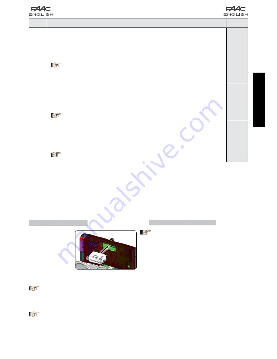
11
Fig. 12
ENGLISH
AS
SERVICE REQUEST - CYCLE COUNTER (combined with the two successive functions):
Y
= when the set number of cycles is reached with successive functions
nc
and
nd
, the
system carries out an 8 sec. preflashing sequence (in addition to the sequence already
set using the
PF
function) before each movement.
no
= successive functions
nc
and
nd
indicate how many cycles the system has performed
up to the maximum possible display of
99.990
.
If the number of cycles is higher than 99.990, the two successive functions
nc
and
nd
will show 99 and 99 respectively.
This function may be useful for setting programmed maintenance operations or for checking
work cycles performed.
no
nc
CYCLE PROGRAMMING (THOUSANDS):
If
AS
=
Y
the display indicates the number of thousands of cycles after which service is
required (may be set from
0
to
99
).
If
AS
=
no
the display indicates the number of thousands of cycles performed. The value
displayed is updated with the sequence of cycles, interacting with the value of
nd
.
If
AS
=
no
press keys + and - for 5 sec. to zero the cycle counter.
00
nd
CYCLE PROGRAMMING (TENS):
If
AS
=
Y
the display indicates the number of tens of cycles after which service is required
(may be set from
0
to
99
).
If
AS
=
no
the display indicates the number of tens of cycles performed. The value displayed
is updated with the sequence of cycles, interacting with the value of
nc
.
Example: if the system has performed 11.218, it will display
nc
= 11 and
nd
= 21
00
St
STATUS OF AUTOMATED SYSTEM:
Exit from programming, data storage, and return to gate status display.
00
= CLOSED
01
= OPEN
02
= Stop then “OPEN”
03
= Stop then “CLOSE”
04
= In “PAUSE”
05
= During opening stage
06
= During closing stage
07
= FAIL SAFE in progress
08
= BUS-2EASY device check in progress
09
= Preflashing then “OPEN”
10
= Preflashing then “CLOSE”
11
= OPEN in Partial Opening
12
= in PAUSE Partial Opening
Display
Function
Default
1
6 STORING RADIO CODE
The electronic device
is equipped with an in-
tegrated dual channel
decoding system (DS,
SLH, LC/RC) known as
OMNIDEC. This system
can use an additional
receiving module (Fig. 5
re.
) and radiocontrols
of the same frequency to store both total opening (OPEN A)
and partial opening (OPEN B) of the automated system.
The 3 types of radio coding (DS, SLH, LC/RC)
can co-exist at the same time on the two
channels. It is possible to enter up to 256
radio codes subdivided between OPEN A
and OPEN B.
To use the different coding systems on the
same channel, finish the learning process
for each system and then repeat the pro-
cedure for another.
6.1 STORING DS RADIOCONTROLS
It is possible to store a maximum of 256
codes divided between OPEN A and OPEN
B/CLOSE.
On the DS radiocontrol, select the required ON - OFF
combination of the 12 dip-switches.
Press and hold down push-button
+
(SW3) or
-
(SW2)
and then press the SETUP push-button (SW4), to store
total opening (OPEN A) or partial opening (OPEN B/
CLOSE) respectively. The corresponding led will begin
to flash slowly for 5 secs.
Release both push-buttons.
Within this 5 second period, press the required push-
button on the radiocontrol.
The corresponding led will come on with a fixed light
for 1 second and then go off to indicate the setting
has been stored.
To add other codes other than the one you have re-
cently stored, repeat the procedure from point 1.
1.
2.
3.
4.
5.
6.


