


11
햲
햳
햴
햵
햶
햸
햷
햹
햺
These instructions apply to the following models:
844 R Reversible
The 844 R Reversible FAAC automated system for sliding gates is
an electro-mechanical operator which transmits movement to
the sliding leaf via a rack and pinion appropriately coupled to
the gate.
The reversible system enables the gate to be moved manually
when the motor is not operating. Consequently, an electric lock
must be installed to ensure locking during closure.
The gearmotor is equipped with an adjustable mechanical
clutch which makes it possible to adjust the thrust force exerted
on the gate.
A handy manual release facility makes it possible to move the
gate in the event of mechanical problems with the gearmotor.
The electronic control unit can be housed inside the operator
(462DF) together with the installation kit, or in a separate
enclosure (578D or 462DF) - see chapter 5.
The 844 Reversible automated system was designed and built
for controlling vehicle access. Do not use for any other purpose.
1.
DESCRIPTION AND TECHNICAL SPECIFICATIONS
Fig. 1
햲
Securing corners
햳
Pinion
햴
Limit sensor
햵
Operator cover
햶
Clutch adjustment
screw
햷
Oil filling plug
햸
Operator earthing
햹
Lever-operated release device
햺
Protective side-panels
1.1.
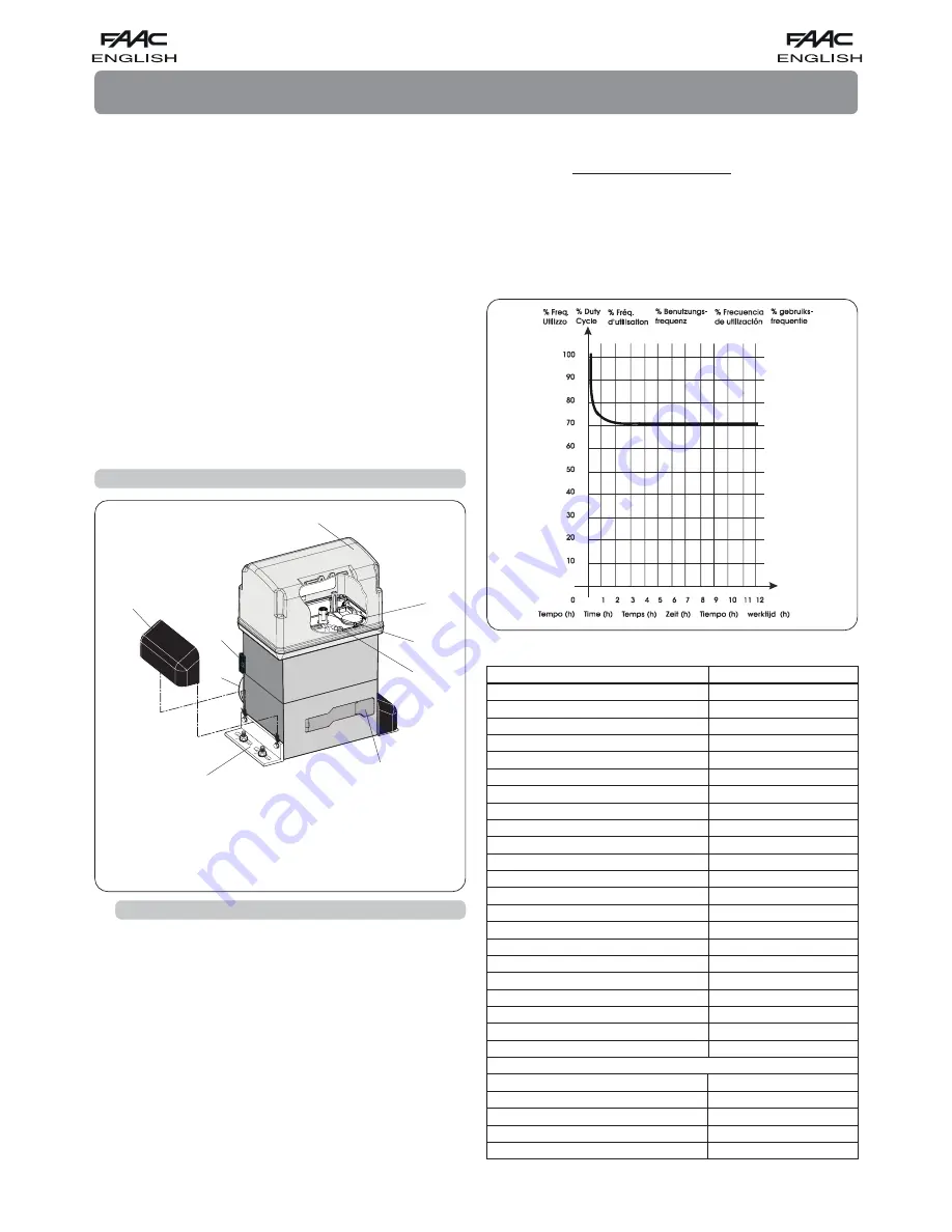
MAXIMUM USE CURVE
The curve makes it possible to establish maximum work time (T)
according to use frequency (F).
E.g.: The 844R Rev. gearmotor can operate non-stop at a use
frequency of 70%.
To ensure efficiency operation, operate in the work range under
the curve.
Important
: The curve is obtained at a temperature of 24°C.
Exposure to the direct sun rays can reduce use frequency down
to 50%.
Calculation of use frequency
The percentage of effective work time (o closing)
compared to total time of cycle (o c pause
times).
where:
Ta = opening time
Tc = closing time
T p = pause time
Ti
= time interval between one complete cycle and another
Use frequency graph
844 R Reversible AUTOMATED SYSTEM
Tab. 1
TECHNICAL SPECIFICATIONS OF GEARMOTOR 844R REV.
MODEL
844 R Reversible
Power supply (Vac +6% -10% 50-60Hz)
Absorbed power (W)
Reduction ratio
Type of pinion
Rack
Max. thrust (daN)
Max. torque (Nm)
Winding thermal protection (°C)
Use frequency
Oil quantity (l)
Type of oil
Operating ambient temperature [°C]
Weight of gearmotor (Kg)
Protection class
Gate max. weight (Kg)
Gate speed (m/min)
Gate max. length (m) (time-out)
Clutch
Protective treatment
Available units
Limit-switch
Gearmotor overall dimensions LxHxD (mm)
Electric motor technical specifications
RPM
Power (W)
Absorbed current (A)
Thrust capacitor (µF)
Power supply (Vac +6% -10% 50-60Hz)
230
550
1 : 10
Z12
module 4 pitch 12.566
68
18
140
70 % (see graph)
1.8
FAAC XD 220
-20 to +55
15
IP 44
1000
11.6
48
twin-disk in oil bath
cataphoresis
578 D - 462 DF
M L S
see Fig. 2
750
550
2.5
25
230
Calculation formula:
Ta + Tc
%F =
X 100
Ta + Tc + Tp + Ti


