21
ENGLISH
ENGLISH
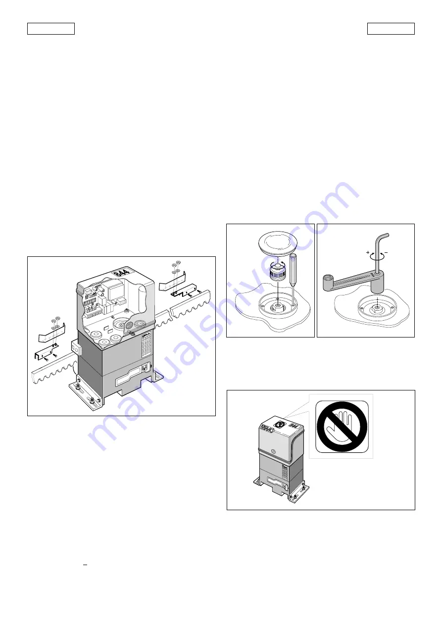
Fig. 34
5.7.
TORQUE ADJUSTMENT
The 844 MC-R automation system is equipped with an anti-
crushing mechanical clutch which stops the opening/closing
movement when the gate encounters an obstacle.
When the obstacle is removed, the gate resumes its movement
until the relevant limit switch trips or the safety time (TIME OUT)
is exceeded.
This torque limiter must be set in compliance with current
standards.
To adjust the threshold of the anti-crushing system, proceed as
follows:
1)
Switch off the power supply.
2)
Remove the cover of the relevant bore (Fig. 1- ref. 9), and
unscrew the cap of the clutch adjusting screw (Fig. 32).
3)
Keep the driving shaft in position by means of the supplied
lever, and adjust the clutch as shown in Fig. 33.
To increase torque, turn the screw clockwise.
To decrease torque, turn the screw counterclockwise.
the operator is supplied with the clutch set to maximum
torque. Initially, the working torque of the system must be
decreased.
4)
Switch on the power supply and check whether the anti-
crushing system trips correctly.
Fig. 32
Fig. 33
6. TESTING THE AUTOMATION
When installation is complete, affix the danger warning label
to the top of the casing (Fig. 34).
Press fit the covers over the operator fixing bars (Fig. 35).
Thoroughly check operation of the automation and all
connected accessories.
Check the closure stop position of the gate and check that the
lock plate is in the correct position. If necessary, change its
position and recheck operation by performing a few gate
movement cycles. When you are sure that the position is
correct, fix the lock plate with screws or by welding.
alarm has been eliminated and the RESET button has been
pressed (or the power supply has been momentarily inter-
rupted).
5.6.
POSITIONING THE TRAVEL STOP PLATE
The 844 MC-R operator is fitted with an inductive proximity limit
switch (Fig.1 - ref.3). When the latter detects the passage of a
plate fastened to the top of the rack, it stops the movement of
the gate.
To position the two travel stop plates correctly, proceed as
follows:
1)
Connect the limit switch connector to the 844MPSR con-
trol unit in accordance with the direction of gate closure
(paragraph 5.2.3. and Figs. 24/25).
2)
Assemble the limit switch, positioning the stop plate cen-
trally relative to the threaded studs of the bracket (Fig.31).
3)
Switch on the power supply.
4)
Move the gate by hand towards it closed position, stop-
ping approximately 2 cm from the physical stop of the
gate.
5)
Set brake-adjusting trimmer TR1 approximately to its cen-
tral position (Fig. 19 - ref. TR1).
6)
Slide the travel stop plate on the rack in the opening
direction. When the LED of the opening travel limit switch
(FCA) in the 844 MPSR electronic control unit (Fig. 28) goes
out, advance the travel stop plate by approximately 45
mm, and fix it to the rack by tightening the screws.
7)
Move the gate by hand towards its closed position, stop-
ping approximately 2 cm from the physical stop of the
gate.
8)
Slide the travel stop plate on the rack in the closing direc-
tion. When the LED of the closing travel end limit switch
(FCC) in the 844 MPSR electronic control unit goes out
(Fig.28), advance the travel stop plate by approximately
45 mm, and fix it to the rack by tightening the screws.
9)
Re-lock the system (see paragraph 5).
10) Run a complete cycle of the gate, to check whether the
limit switch trips correctly. To adjust the limit switch posi-
tions, operate brake trimmer TR1: when the trimmer is
rotated clockwise, the braking space is decreased; when
the trimmer is rotated counterclockwise, the braking space
is increased.
Notes on positioning the travel stop plates
•
The distance between the limit switch and the travel stop
plate must be < 5mm (Fig.11).
•
To avoid damaging the operator and/or interruptions to
service, leave a distance of at least 2 cm
from the physical
stops of the gate.
Fig. 31


