5
2)
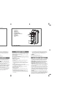
Secure the operator to the rear attachment with the
supplied screws (Fig. 6).
3)
Screw, halfway down, the front attachment onto the rod
(ref.
Fig.8) and tighten with the supplied nut.
4)
Release the operator (see chapter 7).
5)
Fully remove the rod to its stop point and make it recede
by about 5 mm (Fig.7).
6)
Relock the operator (see chapter 8).
7)
Fit the front attachment onto the rod (ref.
Fig. 8)
8)
Close the gate leaf and, keeping the operator perfectly
horizontal, find the position of the front attachment (Fig. 9)
on the leaf.
9)
Provisionally fix the front attachment on the leaf with two
weld spots, protecting the rod against any welding waste.
NB.:
If the gate structure does not permit the attachment to
be firmly fastened, take action on the structure, creating
a solid support base.
10)
Release the operator and manually check if the gate is
free to open completely stopping on the travel limit
mechanical stops and if leaf movement is good and
friction- free.
11)
Definitively weld the front attachment on the leaf.
To do this, temporarily release the operator from the
attachment to prevent welding waste from damaging it
(Fig.10).
Notes:
A)
We advise you to grease all the securing pins of
the attachments.
B)
If welding is impossible, the plates of the front and
rear attachments are designed to be secured with
screws if necessary.
Fig. 9
Fig. 6
Fig. 7
Fig. 10
Fig. 8