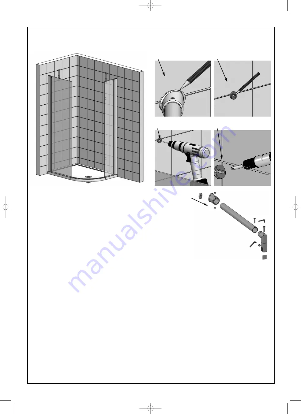
1. Assemble the straight section of the brace bar onto the Low Level brace assembly and fasten together with the
countersunk screw: then slide the wall cup assembly onto the other end of the brace bar.
2. Position the full bracing assembly onto the panel but do not fix at this stage, slightly loosen the allen screw in
the low level bracing assembly so that it can be turned to achieve the correct angle
•
No metal should touch the glass, the spacers must be used.
3. Slide the whole assembly up to the tiled wall to determine the position of the wall cup. Mark around the cup
using a pencil.
4. Unscrew the brass insert from the end of the wall cup and position it in the centre of the pencil mark that you
have just done. Mark through the slot for the position of the screw hole that is to be drilled.
5. Drill the location hole for the wall cup using a 6mm masonry drill (not supplied) and insert the wall plug.
6. Fix the brass insert to the wall using the 40mm screws (supplied) and then screw the wall cup onto the brass
insert so that it is tight up to the tiled walls.
7. Assemble the bracing bar back onto the panel and into the wall cup
•
No metal should touch the glass, the spacers must be used.
8. When you are satisfied that the brace bar has been positioned correctly, tighten all the screws on the wall cup
and on the low level brace assembly with an allen key.
9. To fit the bracing on the other panel simply follow steps 1 to 8.
•
There is 18mm of adjustment in the brace bar to allow for correct alignment.
•
Both panels must be vertically level, make sure the bracing is adjusted to achieve this.
Step 4 - Assembling the Brace Bars (If you are fitting with intergrated water
delivery, please refer to your valve instructions for this step)
➂
➃
➄
➀
➆
➅
FA - Freedom Arc Dec 2009:CQB
4/5/10
12:05
Page 5


