


Chapter 4
Switch Hardware and Functionality
4 - 14
ARX-2000 LED Indicators
This section describes the ARX-2000 LEDs, including:
•
ARX-2000 Status and Alarm LEDs, on page 4-14
•
ARX-2000 Ethernet Port Link Status LEDs, on page 4-16
•
ARX-2000 Ethernet Management Port LEDs, on page 4-17
•
ARX-2000 Power Supply LEDs, on page 4-17
The following table defines the various LED states.
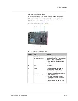
ARX-2000 S
tatus and Alarm LEDs
The lower left of the front panel contains the LEDs shown in the following
figure. For details on the functions associated with each LED, see
Table 4.12
.
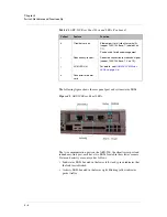
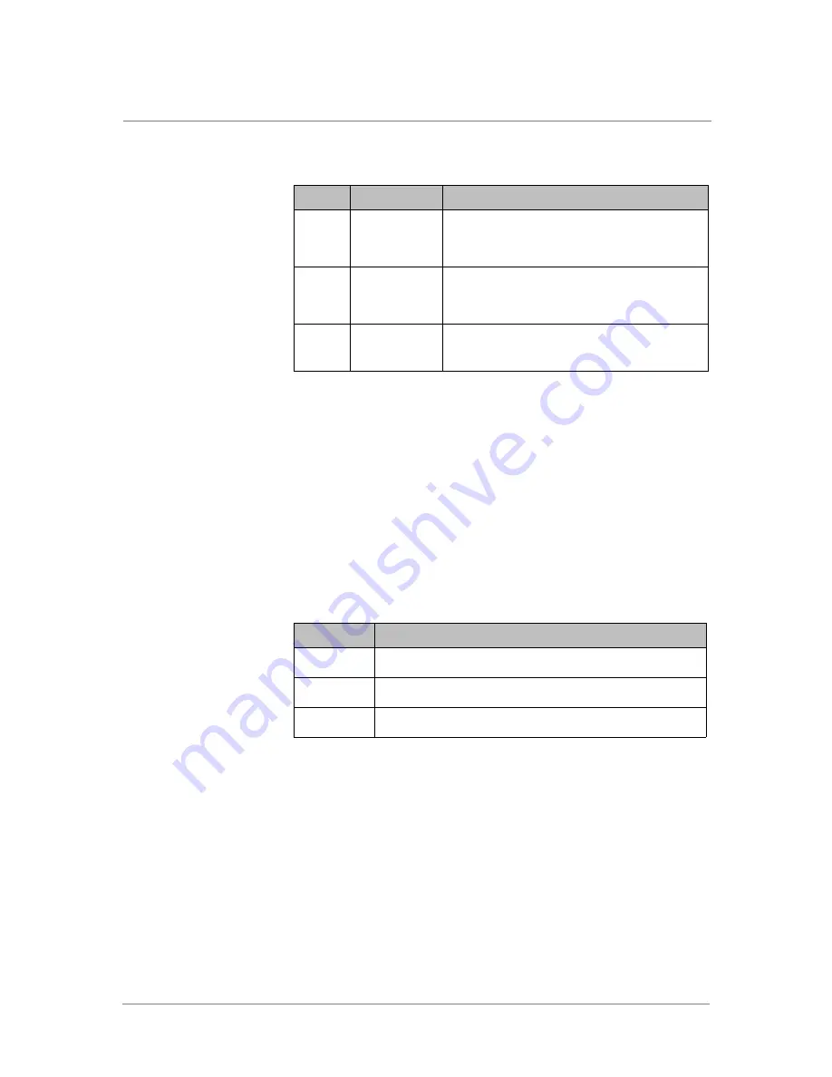
Table 4.11
ARX-2000 Back Panel Components
Callout
Component
Description
A
Serial console
port
Used to access and manage the switch through a
local console terminal and the command-line
interface (CLI).
B
Out-of-band
management
port
Used to access the CLI or the GUI from the
management network.
C
Power supplies
and fans
2 power supplies (1+1 redundancy).
There is a fan on each power supply.
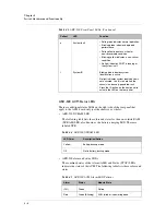
Table 4.12
ARX-2000 LED Definitions
LED State
Definition
Blinking
LED turns on and off at a steady rate.
Flashing
LED is off most of the time. Occasionally, the LED lights.
Flickering
LED turns on and off at an erratic (not constant) rate.
Summary of Contents for ARX-2000
Page 1: ...ARX Hardware Reference Guide MAN 0338 00 ...
Page 2: ......
Page 6: ...vi ...
Page 7: ...Table of Contents ...
Page 8: ......
Page 12: ......
Page 26: ...Chapter 1 Introduction 1 16 ...
Page 27: ...2 ARX Overview ARX Functional Overview ARX Platform Models Managing the Switch ...
Page 28: ......
Page 36: ...Chapter 2 ARX Overview 2 10 ...
Page 37: ...3 System Specifications System Specifications System Power Requirements Cable Requirements ...
Page 38: ......
Page 56: ......
Page 87: ...Index ...
Page 88: ......


