Extron electronics XTP T USW 103 4K User Manual Download Page 9

XTP T USW 103 4K Switcher • Introduction

1

Introduction

This section contains general information about this guide and the Extron 
XTP T USW 103 4K Switcher. Topics in this section include:

• 

Guide Overview

• 

Product Description

• 

Features

Guide Overview

This guide provides installation, operation, control, and reference information for the  
XTP T USW 103 4K Switcher primarily in point-to-point applications. 

NOTE:

  See an XTP matrix switcher user guide at 

www.extron.com

 for matrix 

applications

In this guide, the terms “switcher” and “XTP T USW 103 4K” are used interchangeably to 
refer to the XTP T USW 103 4K Switcher.

Product Description

The Extron XTP T USW 103 4K is a three input universal switcher with an integrated XTP 
transmitter that sends HDMI, DisplayPort, or digitized analog video, audio, bidirectional 
RS-232 and IR, and Ethernet up to 330 feet (100 meters) over a single shielded twisted 
pair cable (STP). It is compliant with HDCP 2.2 (HDMI) or HDCP 1.3 (DisplayPort) standards 
and supports video signal resolutions up to 4K. The XTP T USW 103 4K works with XTP 
Systems for signal distribution and long-distance transmission between XTP devices.
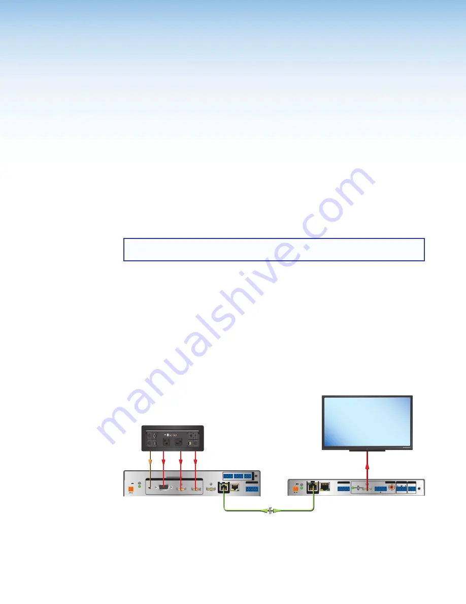
The following diagram shows one way the XTP T USW 103 4K can be integrated in an XTP  
point-to-point application.

LAN

SIG                 LINK

XTP IN

POWER

12V
         

HDMI

1A MAX

Rx G

Tx

RS-232 

IR

Rx

Tx

+

+

L

R

1

2

OVER  XTP

AUDIO

OFF

ON

S/PDIF

RESET

RS-232

Tx Rx G

REMOTE

RELAYS

OUTPUTS

AUDIO

Extron 

XTP SR HD 4K

XTP Scaling Receiver 

Extron

Cable Cubby 1200

Cable Access Enclosure

Extron 

XTP T USW 103 4K

Switcher

SIG           LINK

LAN

XTP OUT

POWER

XTP T USW 103 4K

12V
         

1.5 A MAX

AUDIO

1

2

3

RGB

HDMI

DISPLAYPORT

HDMI OUT

Rx G

Tx

RS-232

IR

Rx

Tx

G

CONTACT

G

RS-232

Tx Rx

1

2 3

TALLY OUT

+V

1

2 3

R

INPUTS

REMOTE

OVER XTP

USB CHARGER

125 VAC. 50-60 Hz 12A MAX

PRES

S

PRES

S

PRES

SP

RESS

Shielded Twisted Pair Cable

up to 330' (100 m)

HDMI

HDMI

DisplayPort

VGA

Audio

4K Display

MODEL 80

FLAT PANEL

Figure 1. 

Typical XTP T USW 103 4K Point-to-Point Application

Summary of Contents for XTP T USW 103 4K

Page 1: ...User Guide XTP T USW 103 4K XTP Systems Three Input Switcher with an Integrated XTP Transmitter 68 2754 01 Rev A 05 17...

Page 2: ...ty and Regulatory Compliance Guide part number 68 290 01 on the Extron website www extron com Sicherheitsanweisungen Deutsch WARNUNG Dieses Symbol auf dem Produkt soll den Benutzer darauf aufmerksam m...

Page 3: ...Lock VN Matrix VoiceLift WallVault WindoWall XTP and XTP Systems Registered Service Mark SM S3 Service Support Solutions Trademarks AAP AFL Accu Rate Frame Lock ADSP Advanced Digital Sync Processing A...

Page 4: ...tion manual may cause harmful interference to radio communications Operation of this equipment in a residential area is likely to cause interference This interference must be corrected at the expense...

Page 5: ...f computer or device responses mentioned in this guide the character 0 is used for the number zero and O represents the capital letter o Computer responses and directory paths that do not have variabl...

Page 6: ......

Page 7: ...n 16 Front Panel Features 16 Front Panel Operation 17 Switch Modes 17 Front Panel Lockout Mode Executive Mode 17 EDID 18 Reset Mode 18 SIS Configuration and Control 19 Host Device Connection 19 SIS Ov...

Page 8: ...XTP T USW 103 4K Switcher Contents viii...

Page 9: ...twisted pair cable STP It is compliant with HDCP 2 2 HDMI or HDCP 1 3 DisplayPort standards and supports video signal resolutions up to 4K The XTP T USW 103 4K works with XTP Systems for signal distr...

Page 10: ...onfiguration Software see Configuration Software on page 27 Certain features can also be controlled through an XTP matrix switcher see the XTP matrix switcher user guide at www extron com NOTE If the...

Page 11: ...h selectable audio control switcher only Features an active HDMI output with support for embedded audio for connection to a local monitor Video mute control Provides the capability to mute video on th...

Page 12: ...t all sources power up properly and reliably outputs content for display Key Minder Authenticates and maintains continuous HDCP encryption between input and output devices to ensure quick and reliable...

Page 13: ...2 3 R INPUTS L A B C D E F G H I J K Input and Output Connectors Interconnection Control and Power Connectors A Analog audio input connector see page 6 B Analog video input connector input 1 see page...

Page 14: ...table below shows the audio format that is sent over the XTP connection when a specific audio format is not specified Default Audio Priorities Selected Video Input Digital Embedded Audio Present Anal...

Page 15: ...s network Ne connectez pas ce connecteur un r seau de donn es informatiques ou un r seau de t l communications G LAN connector Connect a control or controlled device to the pass through LAN connector...

Page 16: ...her contact closure or front panel selection the corresponding tally out pole shorts to ground closing the circuit and lighting the connected indicator LED This connector can also be used with Extron...

Page 17: ...ure 5 15 Pin HD Connector Pins 15 Pin HD Connector Pinout Pin RGBHV RGBs RGsB 1 Red Red Red 2 Green Green Green Sync 3 Blue Blue Blue 4 5 6 Red return Red return Red return 7 Green return Green return...

Page 18: ...t to be placed over it The screw does not have to be removed 3 Place the LockIt on the screw and against the HDMI connector 3 and then tighten the screw to secure the bracket 4 Loosely place the inclu...

Page 19: ...sion am lior e UTP23SF d Extron ou le c ble STP201 pour relier les produits XTP To ensure FCC Class A and CE compliance STP cables and STP connectors are required Afin de s assurer de la compatibilit...

Page 20: ...termination standards NOTES Do not use standard telephone cables Telephone cables do not support Ethernet or Fast Ethernet To avoid transmission errors do not stretch or bend the cables Crossover cab...

Page 21: ...the RS 232 and IR Over XTP Connector ATTENTION The length of the exposed wires in the stripping process is critical ATTENTION La longueur des c bles expos s est primordiale lorsque l on entreprend de...

Page 22: ...h the provided power supply if necessary see figure 10 for wiring considerations SECTION A A A A Power Supply Output Cord 2 Pole Captive Screw Connector Ridges Smooth Tie Wrap 3 16 5 mm Max Figure 10...

Page 23: ...icable provisions of National Electrical Code ANSI NFPA 70 article 725 and the Canadian Electrical Code part 1 section 16 The power supply shall not be permanently fixed to a building structure or sim...

Page 24: ...Front Panel A Auto Switch LED indicator Lights when the switcher is in auto switch mode B Configuration port Connect a host device to the front panel USB mini B configuration port C Input selection bu...

Page 25: ...TP System Configuration Software Auto switch mode The auto switch mode set from the front panel buttons automatically switches to the highest numbered input with an active video signal To enable this...

Page 26: ...e factory shipped firmware SIG LINK LAN XTP OUT POWER XTP T USW 103 4K 12V A MAX AUDIO 1 2 3 RGB HDMI DISPLAYPORT HDMI OUT Rx G Tx RS 232 IR Rx Tx G CONTACT G RS 232 Tx Rx 1 2 3 TALLY OUT V 1 2 3 R IN...

Page 27: ...232 connector see figure 2 H on page 5 The protocol for the serial port is as follows 9600 baud no parity 8 data bits 1 stop bit no flow control SIS Overview Host and Device Communication SIS commands...

Page 28: ...as valid the responses returned to the host a description of the command function or results of executing the command and some examples of commands in ASCII NOTE Uppercase and lowercase text are inte...

Page 29: ...fmtIX Set the audio input format to X View audio input format EIAFMT AfmtIX Analog audio input level NOTE Gain and attenuation commands are case sensitive Audio level commands are not case sensitive S...

Page 30: ...rement value E PHAS PhasX Increase the pixel phase by one Decrement value E PHAS PhasX Decrease the pixel phase by one View pixel phase value EPHAS PhasX Show the pixel phase value Horizontal shift Se...

Page 31: ...DID X1 to input X View EDID Information EAX EDID EdidAX X1 View EDID variable for input X NOTES X1 Preset number 1 to 8 X1 EDID emulation X1 Resolution Refresh Rate Video Format Audio 1 1280x720 60 Hz...

Page 32: ...1 X1 MUTM MutmX1 X1 Mute or unmute all outputs and set the Tally ouput LED setting View AV mute mode EMUTM MutmX1 X1 NOTES X1 Output selection 1 HDMI output 2 twisted pair output 3 HDMI and twisted pa...

Page 33: ...the content on non HDCP compliant displays Enable the HDCP Authorized feature EEX1 1HDCP HdcpEX1 1 Set HDMI input X1 as an HDCP authorized device Disable the HDCP Authorized feature EEX1 0HDCP HdcpEX1...

Page 34: ...presence 0LS FrqX2 1 X2 2 X2 3 View the input signal presence of each input The superscript number next to the X2 variables refer to the input number View HDCP input EIHDCP HdcpI0X2 2 X2 3 View the H...

Page 35: ...le Topics in this section include the following Software Installation Software Connection Software Operation Software Installation The XTP System Configuration Software is compatible with most Microso...

Page 36: ...red in the let sidebar click the XTP System Configuration Software link to go directly to the product page see Software Product Page on the next page Figure 14 XTP System Configuration Software Downlo...

Page 37: ...ration Software from this page perform the following 1 In the Search field see figure 15 1 type XTP System Configuration Software 2 Press Enter on the keyboard or select XTP System Configuration Softw...

Page 38: ...nel configuration port see figure 11 B on page 16 Figure 16 Connections Screen To connect to a device 1 Open the XTP System Configuration Software The Connections screen opens 2 On the Connections scr...

Page 39: ...ct Disconnect The Connections screen opens NOTE If the device is already disconnected the Disconnect option is disabled until a device is connected Exit This option disconnects the switcher from the s...

Page 40: ...ons Select file from computer Uploads a manually selected firmware file saved on the connected computer Check network for updates Checks the connected network for firmware updates If any are found cli...

Page 41: ...is option provides basic information about the XTP System Configuration Software including version number and copyright information Figure 23 About XTP System Configuration Software Dialog Box Example...

Page 42: ...Input selection Click an Input button to select an input As a new input is selected the summary within the panel changes to reflect the currently selected input NOTE The signal indicators on the AV i...

Page 43: ...P Authorized checkbox to enable or disable the HDCP Authorized feature for the associated input This feature determines if a digital input reports as an HDCP authorized sink to a source NOTE HDCP auth...

Page 44: ...eld or click the Up and Down arrows Shift panel Shifting moves the position of an image 3 Horizontal and Vertical Shift To adjust the horizontal and vertical shift settings enter a value within the Mi...

Page 45: ...drop down list select the format for inputs 2 and 3 They can be Auto Digital or Analog 3 Analog Audio Gain Click and drag the handle of the Gain slider enter a value in the field or click the Up or Do...

Page 46: ...ive input number radio button to automatically switch to the highest numbered active input Click the Priority to lowest active input number radio button to automatically switch to the lowest numbered...

Page 47: ...ngs 1 Model Displays the device model 2 Firmware Version Displays the full firmware version 3 Selected Input Displays the input number of the currently selected input 4 Auto input Switching Displays t...

Page 48: ...in blue Connected output resolutions and devices are displayed in green Custom loaded or saved EDID options are displayed in yellow Figure 29 EDID Minder Screen Assign EDID To assign EDID to selected...

Page 49: ...setting is copied to the Favorites panel see figure 29 2 Right click the desired EDID and select Copy Then Paste the EDID setting into the Favorites panel EDID filters The filters see figure 30 can b...

Page 50: ...install the device to a rack follow the mounting kit instructions and see the UL guidelines for rack mounted devices below UL guidelines for rack mounted devices The following Underwriters Laboratori...

Page 51: ...it for example the use of power strips Firmware Download Figure 31 Downloading Firmware from the Extron Website 1 On the Extron website www extron com click the Download tab see figure 31 1 2 On the l...

Page 52: ...pe Hanzeboulevard 10 3825 PH Amersfoort The Netherlands China Extron China 686 Ronghua Road Songjiang District Shanghai 201611 China Asia Extron Asia Pte Ltd 135 Joo Seng Road 04 01 PM Industrial Bldg...

Reviews: