Extron electronics TeamWork 400 Kits Installation Manual Download Page 8


TeamWork Kits • Installation Guide (Continued)

8

“Show Me” Cables

The Extron “Show Me” cables are for use with Extron TeamWork systems. They feature a Share button for remote 
input source selection and a control pigtail, which may be wired directly into Extron switchers with contact closure 
and tally outputs.

HDMI “Show Me” cable

INPUT

(to source device)

Top of Cable Cubby

OUTPUT 

(to switcher)

Bottom of

Cable Cubby

Share Button

Three-conductor 

pigtail for contact 

closure and tally

VGA “Show Me” cable

SHAR

E

INPUT

(to source device)

Top of Cable Cubby

OUTPUT 

(to converter)

Bottom of

Cable Cubby

Share Button

Three-conductor 

pigtail for contact 

closure and tally

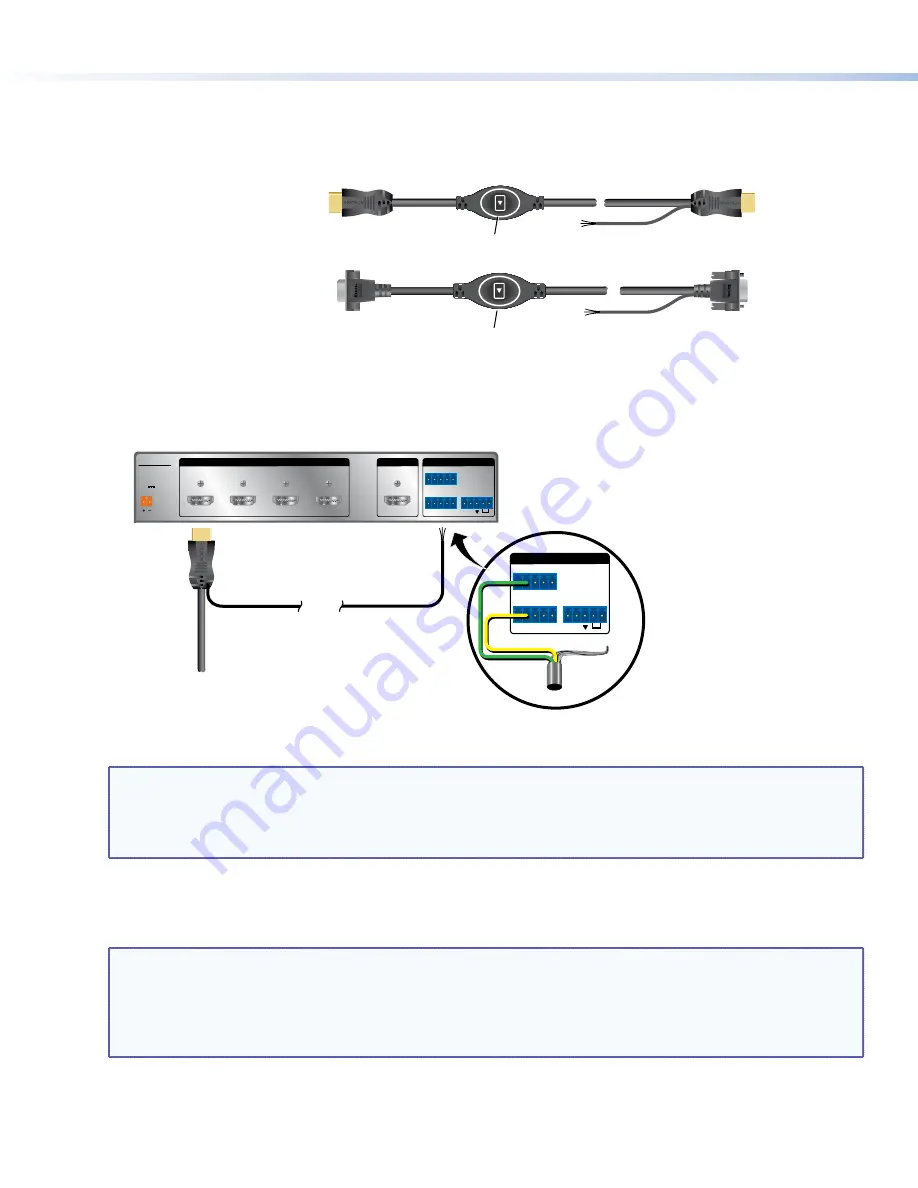
HDMI “Show Me” Cables

1. 

Connect the input end of the “Show Me” cable to the source device.

2. 

Connect the HDMI output to the Extron switcher.

SHOW ME CABLE

SWITCHER END 

(output)

Male HDMI connector

Three-conductor 

pigtail for contact 

closure and tally

0.4A MAX

POWER

12V

1

Tx Rx

RS-232   AUTO

2

3

4

INPUTS

SW4 HDMI

REMOTE

1 2 3 4 G

CONTACT

1 2 3 4

+v

TALLY OUT

OUTPUT

Extron SW4 HDMI Switcher (HDMI input)

Tx Rx

RS-232   AUTO

REMOTE

1 2 3 4 G

CONTACT

1 2 3 4

+v

TALLY OUT

Green

Yellow

Pigtail

Drain wire

(not used)

3. 

Connect the Green (Tally Out) and Yellow (Contact) pigtail wires as shown above. The number under the Tally Out 
and Contact pins must correspond to the video input on the switcher.

NOTES:

• 

The drain wire does not need to be wired to the switcher. The “Show Me” cables are grounded via the 
video connectors.

• 

Do not connect the “Show Me” cable to the +V pin on the Extron switcher.

Press the Share button to switch the connected source to the main presentation display.
Pressing the Share button creates a momentary contact closure, which triggers the switcher to select the 
connected source device. If a tally output is available, the button will light up blue.

NOTES:

• 

The source device provides the +5 VDC supply voltage needed to illuminate the Share button. If the 
source device does not supply this +5VDC, the Share button will not illuminate. Some mobile devices do 
not provide the required voltage to light up the button.

• 

Digital “Show Me” cables support embedded audio and CEC signals.

Summary of Contents for TeamWork 400 Kits

Page 1: ...Panel AC Cord Contact Closure Tally Regional Sales 0 30 60 90 120 150 SOUTH NORTH EAST WEST The diagram above shows a typical TeamWork 400 application The input devices laptops and a tablet connect to the switcher using Show Me cables The Show Me cables allow the user to select the active input on the switcher A control cable connects the RS 232 ports on the switcher and the system controller The ...

Page 2: ...imultaneously for two seconds 0 3A MAX POWER 12V 1 Tx Rx RS 232 AUTO 2 3 4 INPUTS SW4 HDMI REMOTE 1 2 3 4 G CONTACT 1 2 3 4 V TALLYOUT OUTPUT 12V 1 0A MAX POWER RS 232 Tx Rx INPUT AUDIO RGB HDMI 300 A HDMI OUTPUT RGB R Y Y B Y SHARE Extron Analog to Digital Converter VGA Show Me Cable Extron HDMI Switcher Contact Closure and Tally Features z z Standard systems support groups of up to four TeamWork...

Page 3: ...wer modules 2 US modules included 4 AC outlets total Sold separately 2 AC outlets total 2 US modules included 4 AC outlets total Sold separately 2 AC outlets total HDMI Show Me cables 4 4 6 6 HDMI cable 1 1 1 1 Switcher control cable 1 1 1 1 Cable Cubby AAP brackets three space 2 pairs 3 pairs 2 pairs 3 pairs Blank AAP plates single space 2 2 2 2 Installation Guide TeamWork Kits Installation Guide...

Page 4: ...ts and integrated speakers work this way Some professional or commercial grade displays do not have integrated speakers and will not support audio playback Typically source devices with HDMI output connectors embed audio onto the HDMI connector NOTES Always check and test compatibility before installation Some systems may require advanced configuration of the system controller and require the disp...

Page 5: ...tail for contact closure and tally ATTENTION The end with the button and LED connects to the input devices and must come out of the top of the Cable Cubby The end with the three conductor pigtail connects to the switcher and must come out of the bottom of the Cable Cubby 1 Assemble the AAP shelf assembly 2 Insert the AAP assemblies into the Cable Cubby from underneath and secure them in position w...

Page 6: ...onductor pigtail can connect to the switcher Shown mounted with optional Extron UTS 100 UTS 150 Under Table Shelf System Secure Show Me Cable to Cable Cubby and create a loop HDMI Video to Display Extron Cable Cubby Cable Access Enclosure HDMI Show Me Cable VGA Show Me Cable IPL T PC1 R 100 TX RX INPUT IR LINK ACT POWER System Controller Switcher VGA Kit optional Power Supplies 2 AC Power To Displ...

Page 7: ...Switcher Extron IPL T PC1 System Controller RS 232 Control Cable Extron HDMI Pro Cable HDMI Video a b c d e f f Flat Panel Display w Integrated Speakers Extron Show Me Cables Flat Panel AC Cord Contact Closure Tally Regional Sales 0 30 60 90 120 150 SOUTH NORTH EAST WEST a Connect the Show Me cables to the source devices b Connect the Show Me cables to the switcher c Connect the switcher to the di...

Page 8: ...MOTE 1 2 3 4 G CONTACT 1 2 3 4 v TALLY OUT OUTPUT Extron SW4 HDMI Switcher HDMI input Tx Rx RS 232 AUTO REMOTE 1 2 3 4 G CONTACT 1 2 3 4 v TALLY OUT Green Yellow Pigtail Drain wire not used 3 Connect the Green Tally Out and Yellow Contact pigtail wires as shown above The number under the Tally Out and Contact pins must correspond to the video input on the switcher NOTES The drain wire does not nee...

Page 9: ... the 3 5 mm TRS audio input on the converter the cable is not provided with the TeamWork VGA kit The audio signal is embedded in the HDMI output signal 5 Connect the Green Tally Out and Yellow Contact pigtail wires as shown above The number under the Tally Out and Contact pins must correspond to the video input on the switcher NOTES The drain wire does not need to be wired to the switcher The Show...

Page 10: ...er The system controller uses an internal power supply Connect the power cord to a wall outlet The TeamWork 600 systems use a 6 input switcher with an internal power supply Connect the power cord to a wall outlet The TeamWork 400 systems use a 4 input switcher with a 12 VDC 1 A power supply which is provided with the switcher ATTENTION Do not connect the power supply to the SW4 HDMI switcher until...

Page 11: ...er When the button on the second Show Me cable is pressed the LED lights blue and the LED on the first cable is switched off 10 Disconnect all the Show Me cables from the source devices After about 30 seconds without an input signal the display should turn off 11 Connect a Show Me cable to a source device and press the Show Me button on that cable As soon as an active video signal is detected the ...

Page 12: ...sentative at www extron com company contactus aspx Cause 5 Problem with Switcher Solution If none of the cables work correctly there may be a problem with the switcher Contact an Extron Support representative at www extron com company contactus aspx Cause 6 The source device does not output 5V Solution This is a problem with the source device HDMI specifications require pin 18 to carry a 5V output...

Reviews: