


TeamWork Kits • Installation Guide (Continued)
4
Display Requirements
The TeamWork system is designed to work with most brands and models of flat panel displays available worldwide.
For optimum performance, consider the following when selecting the displays for your TeamWork installation. The
display should be tested thoroughly prior to installation or mass deployment of TeamWork systems.
Power attributes
— The system works by controlling AC power to the display. When the display is in the ON
state with an HDMI input selected, it must be able to power back ON to the same HDMI input when AC power
is disconnected and reconnected. If the display doesn’t behave this way, an alternate display should be used.
Alternatively, you may need to control the display a different way (i.e. RS-232, infrared, or via Ethernet) using a
different type of Extron control processor.
Sleep mode
— if the display has a Sleep Mode feature (sometimes called ‘auto sleep’), it must be disabled. Many
displays have an option to disable this within the menu settings.
Resolution
— The TeamWork systems were designed for use with flat panels having an HDMI input connector and
having a native resolution of 1080p. Many of the readily available consumer and professional displays support 1080p
natively.
Audio
— Audio from source devices is supported in the TeamWork system by routing it as an embedded audio
signal to the display for playback via integrated speakers. Most displays with HDMI inputs and integrated speakers
work this way. Some professional or commercial grade displays do not have integrated speakers and will not support
audio playback. Typically, source devices with HDMI output connectors embed audio onto the HDMI connector.
NOTES:
•
Always check and test compatibility before installation. Some systems may require advanced configuration of
the system controller and require the display to be controlled by RS-232, Ethernet, or Infrared.
•
Some displays support a lockout of local buttons. Extron recommends that, after setup, user accessible
controls are locked whenever possible. This ensures the display remains optimized for the TeamWork system.
0.3A MAX
POWER
12V
1
Tx Rx
RS-232 AUTO
2
3
4
INPUTS
REMOTE
1 2 3 4 G
CONTACT
1 2 3 4 +V
TALLYOUT
OUTPUT
12A MAX
POWER OUTPUT 12A MAX
Tx
LAN
Rx
+5V
INPUT
IR
COM
100-120VAC 50/60Hz
IN
S G
US
LISTED 17TT
AUDIO/VIDEO
APARATUS
®
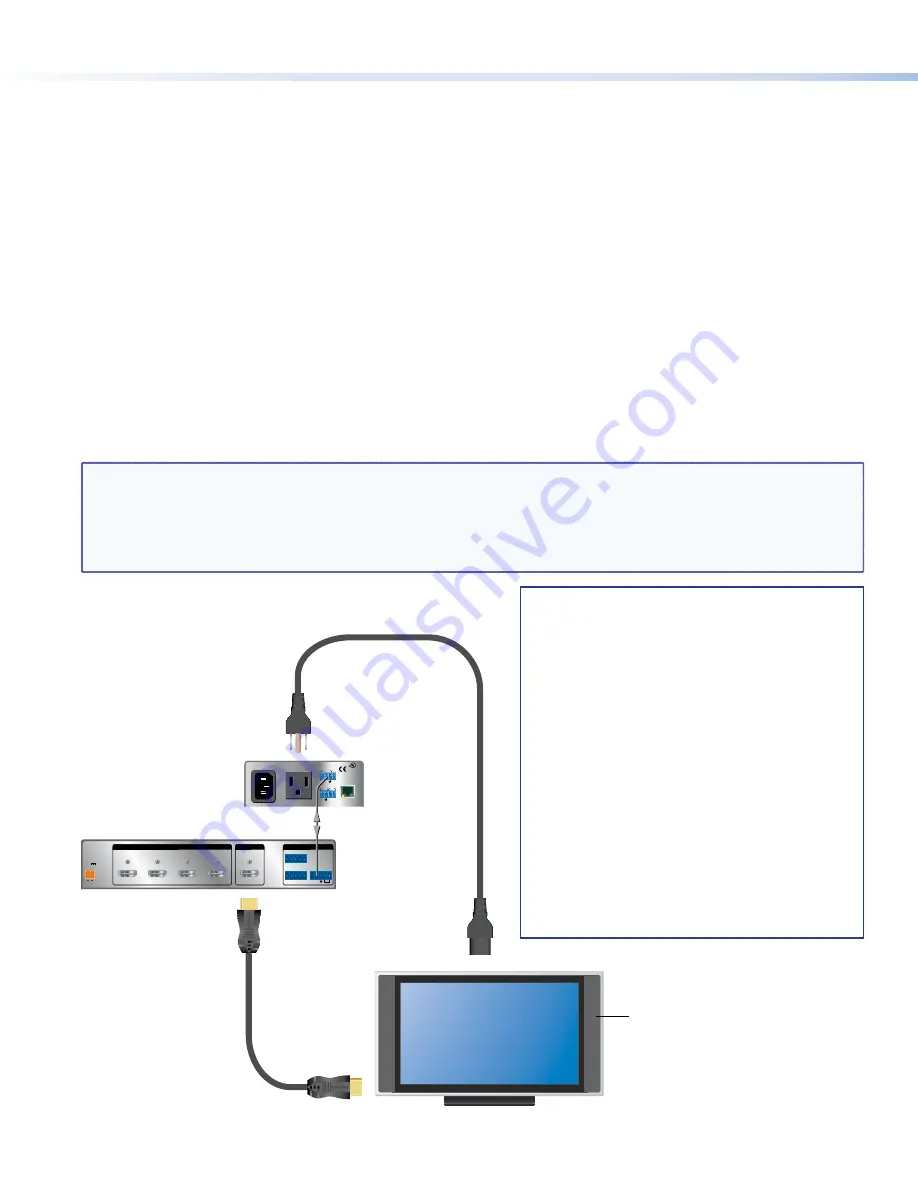
Extron
HDMI Switcher
Extron
System
Controller
RS-232
Switcher Control
AC Power
1080p Native
Resolution Display
Display should have an HDMI
input and support embedded
audio.
For Audio Playback
display should have
integrated speakers.
Teamwork Systems work
by controlling AC power
to the display.
TeamWork systems require a display that
returns to the previous state when the
power cord is disconnected and then
plugged back in.
How to check if a display is compatible:
1.
Apply AC power to the display.
2.
Turn the display ON.
3.
Select the HDMI input.
4.
Adjust the volume.
5.
Unplug the display (remove AC power).
6.
Re-apply AC power to the display.
If the display powers back up (to the ON state)
and to the same input and volume level, the
display will work with the TeamWork system.


