SW DVI Plus Series • Installation
10
Remote/Auto-SW
Computer or
Control System
RS-232 Port
SW DVI Plus Switcher
Rear Panel RS-232 Port
NOTE:
If you use cable that has a drain
wire, tie the drain wire to ground
at both ends.
Tx Rx
_
A S
Ground (
_
)
Transmit (Tx)
Receive (Rx)
Transmit (Tx)
Receive (Rx)
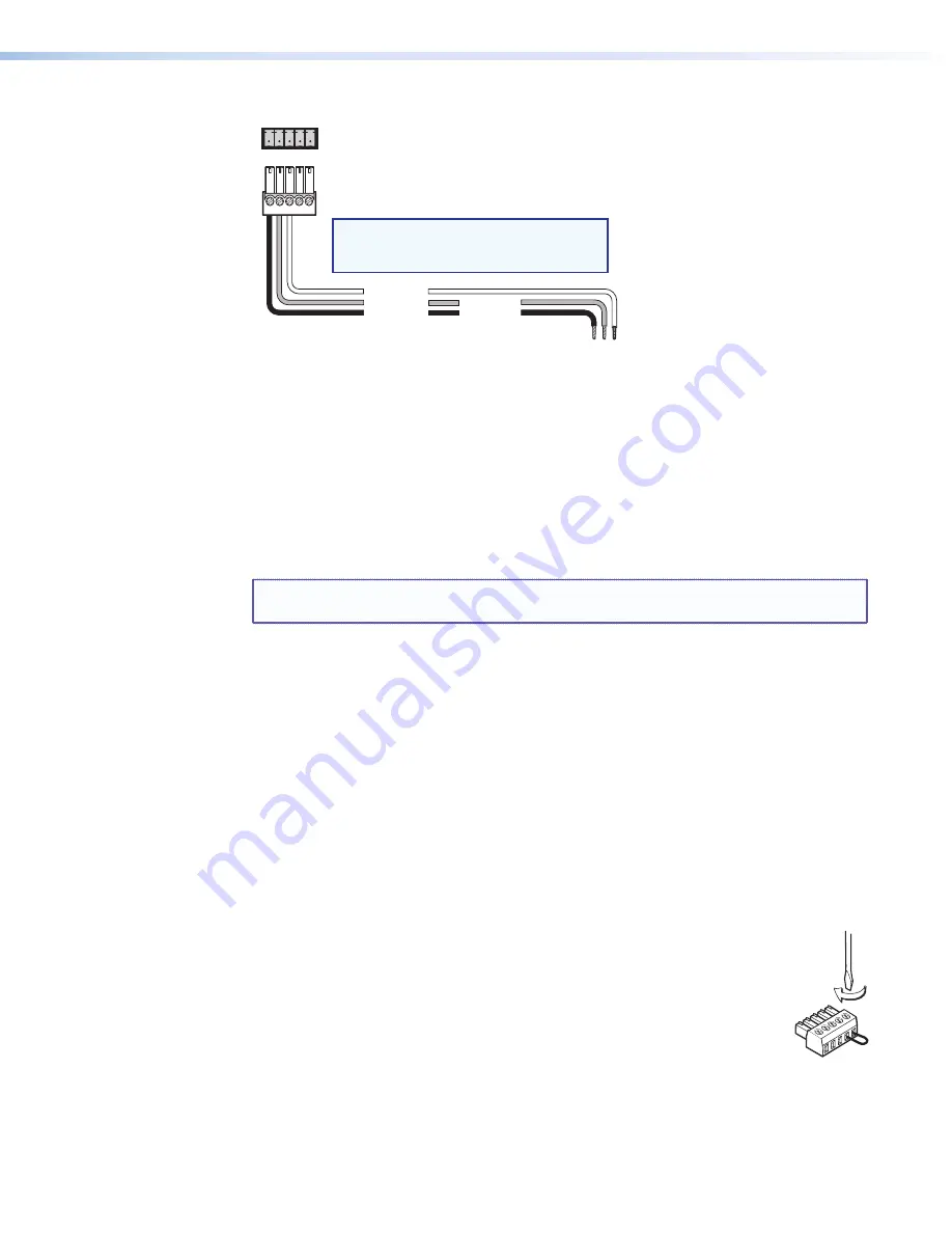
Figure 12.
Remote/Auto-SW Connector Pin Assignments for RS-232
Enabling Auto-input Switching
You can set up the SW DVI Plus to automatically select the active connected input based on
detection of a video sync signal. If two or more inputs are active, the input with the highest
number is selected (for example, input 8 on an SW8 DVI Plus switcher). When auto-input
switching is in effect, the green Auto Switch LED on the front panel lights and the front
panel input selection buttons are disabled.
NOTE:
Audio and video cannot be switched separately when auto-input switching is
enabled.
SW2/SW4 DVI Plus (Non-audio) Models
On the non-audio SW2 and SW4 DVI Plus, auto-input switching is enabled or disabled via
the following SIS commands (see the “
Remote Configuration and Control
” section,
beginning on page 18, for information on using SIS commands).
•
1#
selects normal switch mode.
•
2#
selects auto-input switch mode.
All Other Models
To enable auto-input switching on the SW2, SW4, SW6, and SW8 DVI A Plus models and on
the SW6 and SW8 DVI Plus non-audio models:
1.
Cut a small piece of wire to use as a jumper.
2.
Insert the ends of the wire into slots 4 and 5 of the provided 5-pole captive
screw plug, connecting pins 4 and 5 together.
3.
Use a small screwdriver to tighten the two screws of the plug above pin
slots 4 and 5, so that the jumper wire ends remain securely in place (see
the illustration at right).
4.
Insert the plug into the 5-pole Auto-SW captive screw connector on the
switcher rear panel.
Figure 13
on the next page shows an SW8 DVI A Plus with a jumper
connecting pins 4 and 5 to enable auto-input switching.


