Extron electronics MLC 226 IP Series Installation Manual Download Page 135


6-17

MLC 226 IP Series • Special Applications

PRELIMINAR

Y

17. 

Click the 

Done

 button at the bottom of the Monitored Conditions Window, 

which then closes.

18. 

Complete the rest of the confi guration as desired, then save the project and 
build and upload the confi guration to the MLC.

Working With a Non-MediaLink Extron Switcher

Although the MediaLink Controller’s MLS port can be used as an auxiliary RS-232 
port for controlling another type of device, it is usually used to connect an Extron 
MediaLink Switcher (MLS) or PoleVault Switcher (PVS).  The MLC recognizes and 
communicates with MLS and PVS switchers without requiring additional drivers or 
confi guration, unless you want to remap switcher inputs to the MLC’s buttons.

The MLC can recognize Extron switchers other than MLS and PVS models, 
but as a single, generic type of switcher.  For example, the MLC considers an 
MPS 112 switcher to be the same as an IN1508 or an SW 4AV.  The MLC supports 
bidirectional communication for input switching and volume control, just as it does 
for the MLS and PVS switchers.

You can control an Extron switcher such as an MPS 112 or MPS 112 CS via the MLS 
port if all of the following conditions are met:

•  The MPS switcher uses fi rmware version 1.12 or higher.

•  The MPS is in single switcher mode.  It must be in single switcher mode (not 

separate switcher mode) to be controlled by the MLC.

•  The MLC uses fi rmware version 1.07 or higher.  This is required in order to 

bidirectionally track inputs greater than 6.

Also, if the input buttons are in input mode, the MLC and MPS buttons track 
bidirectionally: an input button press on one device is indicated on the other device.

To set up the MLC to control an MPS 112 Series switcher, cable the MLC and 
connect the MPS switcher to the MLC’s MLS port, then follow these steps:
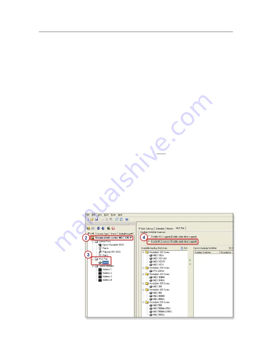
1. 

Create a new Global Confi gurator project that includes an MLC.

2. 

In the IP Link tree view window, click on the MLC to be confi gured.

Summary of Contents for MLC 226 IP Series

Page 1: ...t Rear Right Side Left Side Bottom rotated 180 degrees 1 D INPUT I O 2 Tx 3 Rx 5 GND 38400 N 8 1 DISPLAY R INTERCOM AUDIO OUT A B C D E DISPLAY RS 232 IR RS 232 12V CM IR SCP A B C D E MLS PWR A B T x I R Rx G RO UN D P W R S N S G RO UN D 12V OUT Rx Tx GROUND GROUND 12V IN 12V OUT GROUND CONT MOD IR IN SCP COM NORMALLY OPEN 1 2 COMMON COMMON COMMON GROUND Tx IR Tx IR Tx IR GROUND GROUND A RELAYS ...

Page 2: ...al verwenden sollten Sie alle Sicherheits und Bedienungsanleitungen genau durchlesen und verstehen Aufbewahren der Anleitungen Die Hinweise zur elektrischen Sicherheit des Produktes sollten Sie aufbewahren damit Sie im Bedarfsfall darauf zurückgreifen können Befolgen der Warnhinweise Befolgen Sie alle Warnhinweise und Anleitungen auf dem Gerät oder in der Benutzerdokumentation Keine Zusatzgeräte V...

Page 3: ...2 3 Bottom rear panel and cabling 2 5 Projector display connections 2 5 Additional control connections 2 6 MLC 226 IP DV connections 2 9 Power connection 2 12 Intercom connection 2 13 Side panel cabling and features 2 13 Resetting the Unit 2 15 Pinout Guide 2 16 Mounting the MLC 2 16 Mounting the MLC to an electrical box or mud ring 2 17 Mounting the MLC to a wall or furniture 2 18 Rack mounting a...

Page 4: ...ation via a Web browser 4 5 Configuring the MLC for network communication using SIS commands 4 6 RS 232 4 6 Telnet 4 6 Setting up the PC for IP communication with an MLC 4 7 Global Configurator Software for Windows 4 9 Downloading the software and getting started 4 9 PC system requirements 4 10 Using Global Configurator helpful tips 4 10 Resources and notes 4 10 A brief guide to Global Configurato...

Page 5: ...s accessible via RS 232 only 5 34 Chapter Six Special Applications 6 1 Using Monitoring to Make Functions Track Actual Conditions 6 2 Prerequisite setup steps 6 2 Setting up the front panel button 6 3 Setting up monitoring conditions 6 4 Working With Combination Source Devices 6 7 Available methods 6 7 Using an IRCM DV control module and one MLC input button for DVD VCR control 6 7 Controlling Two...

Page 6: ...ining the Firmware Version B 2 Using the Global Configurator software B 2 Using a Web browser B 2 Updating the Main Firmware B 4 Locating and downloading the firmware B 4 Updating firmware via the MLC s embedded Web page B 4 Updating firmware via Extron Firmware Loader software B 5 Updating firmware via Extron IP Link File Manager software B 7 Resetting the MLC and restoring its configuration B 9 ...

Page 7: ...PRELIMINARY MLC 226 IP Series 1 Chapter One Introduction About the MLC 226 IP Series MediaLink Controllers How the MLC 226 IP Series Controllers Work MLC Components and Interactions ...

Page 8: ...ls can make use of the controller s embedded Web pages which include online diagnostics and monitoring of basic control features As an integrated part of the MLC 226 IP IP Link provides the following advantages Global compatibility The MLC uses standard Ethernet communication protocols including ARP DHCP ICMP ping TCP IP Telnet HTTP and SMTP Embedded Web page serving The MLC 226 IP offers up to 7 ...

Page 9: ...r Extron SI 26 Surface Mount Speakers Projector Control Laptop w Audio Document Camera VCR DVD Projector PC Help Desk PC RGBHV S video Video Extron MLC 226 IP AAP MediaLink Controller Extron IPI 104 AAP Intercom A typical application for an MLC 226 IP MediaLink Controller System Requirements The MLC 226 IP and Global Configurator have the following hardware and software requirements Hardware requi...

Page 10: ...Program or Web Browser MLC 226 IP Memory IR 402 Control Modules SCP SCP Lights The MLC can be configured completely via the Extron Global Configurator software Once you have set up how you want it to work assigned drivers to ports configured buttons and relays and set up IP addresses and functions that information is saved to a project file that is uploaded into the MLC The configuration informati...

Page 11: ...PRELIMINARY MLC 226 IP Series 2 Chapter Two Installation UL Safety Requirements Installing or Replacing Button Labels Panels and Cabling Resetting the Unit Pinout Guide Mounting the MLC ...

Page 12: ...onal SCP control panel you may wish to customize the button labels The labels can be changed at any time Follow these steps to change the translucent button labels 1 Remove the button from the MLC or SCP use a small flat bladed screwdriver such as an Extron Tweeker to gently pry a button out from the front panel 2 Locate the notch in the corner of one side of the clear button cap 3 Separate the wh...

Page 13: ...d for digital input output RS 232 protocol 38400 baud 1 stop bit no parity 8 data bits no flow control DB9 Pin Locations Female 5 1 9 6 N Extron recommends configuring and controlling the MLC via the LAN connector Ethernet connections are faster and more reliable Pin RS 232 function Description 1 Digital I O Digital input output 2 Tx Transmit data 3 Rx Receive data 4 No connection 5 Gnd Signal gro...

Page 14: ...accepting 250 mA maximum When the port is set to the off state the circuit is open the output pin is floating If the application calls for TTL compatibility the circuit can be set up to provide a 2k ohm pull up resistor to 5 VDC b Front panel Config host control port This 2 5 mm mini stereo jack serves the same RS 232 function as the rear panel Host Control port but it is easier to access than the...

Page 15: ...and display power sensor port b CM IR SCP port c Relay ports 24 V 1 A d IR Serial Output ports e MLS connector f PWR power connector g Intercom connectors Projector display connections a Display control Display RS 232 IR port 5 VDC to 5 VDC Connect a cable between the projector or display and the left three poles of this 3 5 mm direct insertion captive screw connector for bidirectional RS 232 cont...

Page 16: ...ion distance Distances of about 50 feet 15 m are typically not a problem In some cases the MLC may be capable of transmitting and controlling a given device via RS 232 up to 250 feet 76 m away but the RS 232 response levels of that device may be too low for the MLC to detect Digital input The power sense Pwr Sns pin and the Ground pin together can act as a digital input port if configured that way...

Page 17: ... D B A E D C B A SCP communication IR Modulated IR from IR Link Ground IRCM ACM RCM 12 VDC C B A Maximum 2 SCPs Per System Maximum 4 Control Modules 4 module addresses Maximum 1 IR Link Ground IRCM ACM RCM 12 VDC Ground and Drain 12 VDC DVD VCR CONTROL PLAY NEXT FWD PAUSE STOP TUNER Tx PREV REW ENTER TITLE MENU TV VCR DVD VCR SCP 226 IR Link SIGNAL IR LINK DISPLAY SCP 226 1 2 3 4 5 6 VOLUME CONFIG...

Page 18: ...ain Wire Ground Drain Wire E D C B A SCP Communication Modulated IR for IR Link Control Module Communication 12 VDC White Black and Drain Wire Violet Red NOTE 2 SCPs Maximum Per System MLC 226 IP Bottom Panel 200 61 m Max to Last Device C IRCM ACM RCM VOLUME SCP 226 IR DISPLAY Extron 1 2 3 4 5 6 ON OFF PIC MUTE AUTO IMAGE VCR DOC CAM PC LAPTOP DVD VOLUME SCP 226 IR DISPLAY Extron 1 2 3 4 5 6 ON OF...

Page 19: ...B WITH TWEEKER TO REMOVE LAN 1 D INPUT I O 2 Tx 3 Rx 5 GND 38400 N 8 1 R INTERCOM AUDIO OUT A D B C E A D B C E Factory wired MLC to IRCM DV Connection An MLC 226 IP DV with SCPs and additional control modules c Relay ports 24 V 1 A These six relays allow control of items such as room lighting window coverings and display screens These contacts may be used to control any equipment as long as the c...

Page 20: ...ed for controlling a device each port must be set up via Global Configurator software for either IR or RS 232 communication and associated with a device driver For RS 232 output 5 VDC to 5 VDC use the illustration below as a wiring guide then wire a serial cable into this captive screw connector RS 232 default protocol 9600 baud no parity 8 data bits 1 stop bit no flow control N Maximum distances ...

Page 21: ...ol e MLS connector For controlling an optional Extron switcher or other RS 232 controllable device connect a cable between this 3 5 mm direct insertion captive screw connector and the RS 232 port of the other device By default this port supports Extron MediaLink and PoleVault switchers listed below without additional drivers If it is used to control other products additional device drivers may be ...

Page 22: ...Y OPEN 1 2 COMMON COMMON COMMON GROUND Tx IR Tx IR Tx IR GROUND GROUND A RELAYS IR SERIAL OUT 3 4 B 5 6 C A B C MLC 226 IP Bottom Panel RS 232 12V MLS PWR A B Rx Tx GROUND GROUND 12V IN Ground Transmit Tx B Receive Rx A Transmit Tx Receive Rx B A Ground 12 VDC input Ground all devices External Power Supply 12 VDC 1 A max External Power Supply Power connection f PWR power connector To provide power...

Page 23: ...port that can be connected to local powered speakers or to any audio or paging system See the wiring guide in the illustration above N The volume for this audio output can be adjusted via IP Intercom HelpDesk software only Side panel cabling and features a LAN IP connector and LEDs An Ethernet connection can be used on an ongoing basis to connect and to control the MLC 226 and the devices INTERCOM...

Page 24: ... See Resetting the Unit in the next section of this manual for details LAN RJ 45 Port Link LED Activity LED LAN RJ 45 Port Link LED Activity LED Clip Down 1 1 2 3 6 4 5 7 8 2345678 12345678 RJ 45 Connector Twisted Pairs Straight through Cable for connection to a switch hub or router End 1 End 2 Pin Wire Color Pin Wire Color 1 white orange 1 white orange 2 orange 2 orange 3 white green 3 white gree...

Page 25: ...econd The MLC reverts to the factory default firmware Event scripting will not start if the MLC is powered on in this mode All user files and settings drivers adjustments IP settings etc are maintained If you do not want to update firmware or you performed a mode 1 reset by mistake cycle power to the MLC to return to the firmware version that was running prior to the mode 1 reset Use the 0Q SIS co...

Page 26: ...an Extron Display Power Sensor OR 12 VDC Ground Power sense To an IR Emitter IR Broadcaster or IR or serial RS 232 controllable device Ground 12 VDC input SCP communication IR Modulated IR for IR Link or IRL 20 Ground IRCM ACM RCM 12 VDC Digital input Ground Signal IR To from optional Extron control modules IR Link IR repeater or SCP control pads Mounting the MLC Once the system has been cabled co...

Page 27: ...u tie a product to two different ground sources you may introduce ground loops or other grounding related problems into the system N For the installation to meet UL requirements and to comply with National Electrical Code NEC the MLC must be installed in a UL approved junction box The end user or installer must furnish the junction box it is not included with the MLC OFF ON DOC CAM LA PTO P PC VCR...

Page 28: ...Do not tie a product s faceplate to both a separate earth ground and the circuit ground via a connector pin If you tie a product to two different ground sources you may introduce ground loops or other grounding related problems into the system N For the installation to meet UL requirements and to comply with National Electrical Code NEC the MLC must be installed in a UL approved junction box The e...

Page 29: ...equipment nameplate ratings should be used when addressing this concern 5 Reliable earthing grounding Maintain reliable grounding of rack mounted equipment Pay particular attention to supply connections other than direct connections to the branch circuit e g use of power strips Mounting the MLC in a Euro Channel 1 Remove the four faceplate attachment screws and remove the original faceplate if app...

Page 30: ...Installation cont d MLC 226 IP Series Installation 2 20 PRELIMINARY ...

Page 31: ...RELIMINARY MLC 226 IP Series 3 Chapter Three Operation Projector Control Front Panel Features and Operation Optional Control Modules and IR 402 Remote Control Front Panel Security Lockout Executive Mode ...

Page 32: ...LC can use IR learning is convenient for installing new or updated commands into the MLC in the field See chapter 4 and the Global Configurator help file or the IR Learner help file for details on setting up the MLC and for downloading programming or learning projector control commands Front Panel Features and Operation N Many features must be set up in order for the MLC to function See chapter 4 ...

Page 33: ...tons can be assigned several functions apiece depending on how the MLC is set up and what mode is active Each button can be configured to control the MLC s relays execute the IR or RS 232 commands of your choice or trigger event scripts and or port monitoring The relays can be used to control items in the room such as a projector lift screen motor or lighting For details on how the relays operate ...

Page 34: ...eassign remap any input from 1 to 99 to these input buttons Button remapping can be convenient if an MLC is hosting a peripheral switcher Volume control d Volume knob and LEDs Rotate this knob clockwise to increase the audio volume counterclockwise to decrease volume Volume can be adjusted via this front panel knob the corresponding knob on an SCP control panel the Volume up down buttons on an IR ...

Page 35: ...er accepts IR signals from the Extron IR 402 infrared remote control which mimics the MLC s front panel controls N If outside interference such as fluorescent lighting affects the MLC s functioning you may need to disable IR control Front panel IR control can be disabled using the 65 special function SIS command See page 5 40 for details f IR learning receiver This smaller sensor receives and lear...

Page 36: ...dules and IR 402 Remote Control The MLC can learn IR commands from a VCR s DVD s tape deck s or other device s remote control allowing you to create an IR driver file that can be incorporated into the MLC s event scripts A command can be associated with each of the buttons on an optional infrared control module such as the Extron IRCM VCR IRCM DVD IRCM DVD or IRCM DV in order to allow limited cont...

Page 37: ... port and IR ports via IR Emitters or optional IR Broadcaster when the corresponding button is pressed on the remote or on the controller s SCP s or control module s front panel Refer to the Control Modules User s Manual Front Panel Security Lockout Executive Mode To prevent accidental changes to settings the MLC features front panel security lockout executive modes for disabling access to control...

Page 38: ...lick on the Configuration tab which opens to the System Settings page 3 Select either Off or Disable Front Panel SCP Control Modules and IR in the Executive Mode settings area See the following picture N If Disable Front Panel SCP Control Modules and IR is selected via the System Settings factory default Web page front panel lockout can t be enabled disabled via the front panel unless PIN Mode is ...

Page 39: ...Controller Unocking the Front Panel of an MLC 226 IP Series Controller 1 1 2 If an incorrect PIN is entered no buttons flash the green Volume LEDs turn off and the red top LED blinks Then the buttons light as they were lit before front panel lockout was set Release all buttons If the correct PIN is entered the green Volume LEDs flash and all buttons flash green 3 times indicating that front panel ...

Page 40: ... instructions 3 In the IP Link tab area on the left side of the screen click on the name of the MLC you want to set up 4 Click on the Advanced Configuration tab 5 Select which PIN to enable which PIN will be allowed to unlock the front panel or disable both PINs so that no one can access the front panel during front panel lockout 6 Type in the four digit PINs for the administrator and for users Ea...

Page 41: ...Extron Global Configurator GC software See chapter 4 2 Open an existing GC project or start a new project Refer to the GC help file or the MLC 226 IP Series Setup Guide for instructions 3 In the IP Link tab area on the left side of the screen click on the name of the MLC you want to set up 4 Click on the Schedule tab in the right side of the screen as shown below 5 Click Add Schedule The Scheduled...

Page 42: ...Click Next 9 Set up the front panel lockout action for the MLC See the illustration on the following page a Check the Action check box b Select the MLC itself from the Subject Ports list c Click on Lockout Front Panel in the Available Options list A default description appears in the Action Name area If desired you can change the name assigned to this action d Click Apply Action e Click Done The S...

Page 43: ... Action check box b Select the MLC itself from the Subject Ports list c Click on Unlock Front Panel in the Available Options list If desired you can change the name assigned to this action in the Action Name area d Click Apply Action e Click Done The Scheduled Actions Wizard window closes 15 Save the project click File and then Save or click the Save icon 16 Upload the project to the MLC a Click t...

Page 44: ...Operation cont d MLC 226 IP Series Operation 3 14 PRELIMINARY ...

Page 45: ...d Control Configuration and Control an Overview The Basic Steps A Guide to this Chapter and Other Resources Configuring the MLC for Network Communication Global Configurator Software for Windows Advanced Configuration Controlling the MLC Customizing the MLC s Control Web Pages ...

Page 46: ...Netscape and Firefox cannot be used for viewing the Serial Control pages of the factory embedded Web page Run Internet Explorer to use those pages The third way to control and configure the controller is by using Simple Instruction Set SIS commands via Telnet a Web browser or RS 232 SIS commands are discussed in detail in chapter 5 The Basic Steps a Guide to this Chapter and Other Resources 1 Conf...

Page 47: ...ge the controller s default settings IP address subnet mask and optional administrator name and password in order to use the unit on an intranet LAN or on the Internet WAN After you have set up the MLC 226 IP for network communication you can reset the PC to its original network configuration MLC 226 IP s RS 232 protocol 38400 baud 8 data bits 1 stop bit No parity No flow control N Both configurat...

Page 48: ...as follows 1 Obtain a valid IP address for the controller from your network administrator 2 Obtain the controller s MAC address UID from the label on its rear top or side panel The MAC address should have this format 00 05 A6 xx xx xx 3 If the MLC has never been configured and is still set for factory defaults go to step 4 If not perform a Mode 4 system reset For detailed information on reset mode...

Page 49: ... the MLC and the PC must both be part of the same subnet before they can communicate via the LAN port You must change the PC s IP address to one that is on the same subnet as the default IP address of the MLC 192 168 254 254 N This method requires a crossover cable See page 2 14 for cabling details 1 Temporarily change the host PC s IP address See Setting up the PC for IP communication with the ML...

Page 50: ...cation with the controller 6 Close the browser 7 After changing the controller s IP settings change your PC s TCP IP settings back to their original configuration Configuring the MLC for network communication using SIS commands RS 232 The MLC can also be configured using serial RS 232 communication and a terminal emulation program such as HyperTerminal which is installed with Windows For informati...

Page 51: ...s the TCP IP protocol must be installed and properly configured When setting up the MLC for network communication via a Web browser or Telnet connection you must change the IP address of the PC to one that is on the same subnet as the MLC This is not required if you are setting up the MLC for network communication via Global Configurator the ARP command or SIS commands via an RS 232 connection If ...

Page 52: ...em for information on how to install the TCP IP protocol 4 Write down the PC s current IP address and subnet mask below If your PC is set to Obtain an IP address automatically make a note of that instead You will need to restore these settings to the PC later IP address Subnet mask 5 Change the PC s IP address so it can communicate with the MLC 226 IP and change the controller s IP settings a Sele...

Page 53: ...provides the ability to generate a Web browser based GlobalViewer GV application and Web pages for each IP Link based device IP Link interface System 5 IP MLC 226 IP MLC 104 IP or other Extron device on a network Once an MLC 226 IP is configured its GlobalViewer Web pages allow the user to manage monitor and control the MLC and the devices connected to it Global Configurator offers the best and ea...

Page 54: ...tium III 1 GHz processor Microsoft Windows operating system Windows NT service pack 4 or Windows 2000 service pack 2 or Windows XP service pack 2 Microsoft Internet Explorer 6 0 with ActiveX enabled Microsoft Windows Script 5 6 512 MB of RAM 50 MB of available hard disk space A network connection with a minimum data transfer rate of 10 Mbps 100 Mbps is recommended C Do not run this software on a P...

Page 55: ...ps of functions you can view and configure The left three IP Link Settings Schedule and Monitor are displayed for all IP Link enabled products Any tabs to the right of those three vary in quantity type and layout depending on the product being configured See the illustration below for an example of the tabs that may be available when you configure an MLC IP Link Settings shows all the IP related s...

Page 56: ...or later in this chapter Auxiliary Port allows you to select and configure a model of MediaLink Switcher MLS or PoleVault Switcher PVS to control using the MLC via the MLC s MLS RS 232 port See Configuring an auxiliary switcher later in this chapter Advanced Configuration IR learning to create customized IR driver files If you do not find a driver on the Extron Web site for the device you plan to ...

Page 57: ...ower on up and power off down cycles Auto shut off period This feature at the top of the Power Settings area lets you set the length of time that the display or projector can be inactive before the MLC automatically turns it off Settings can be 30 to 720 minutes or 0 I O switching delay periods The second item in this area controls whether and how long to prevent lock out input switching after an ...

Page 58: ... to press and hold the Display Off button for two seconds to start the display power down process This prevents users from shutting down the display or projector by accidentally pressing the button Volume settings When adjusting the volume use Volume control for a projector display or audio output device involves one of two methods selecting a setting within a specific range of values or sending a...

Page 59: ...gs Digital input output port 1 consists of pin 1 and the ground pin of the rear panel Host Control 15 pin HD connector For digital I O port 1 you can choose one of the four options shown at right for how the port will function See pages 2 3 to 2 4 for details on wiring and using this port Digital input port 2 consists of the power sense Pwr Sns pin and the Ground pin of the bottom panel Display RS...

Page 60: ... select the Enable MLS Support radio button If the MLC and its attached MLS or PVS switcher are powered on and connected to the network GC automatically detects the switcher and you can skip to step 4 If not proceed to step 2 2 Click on a switcher s model name in the Available Auxiliary Switchers area 3 Click the Add button 4 Click the Configure button or double click the switcher s name in the Cu...

Page 61: ...gs window select click on the desired MLC in the list that appears on screen 5 Click Settings and choose Set Administrator Password from the drop down menu as shown at right A Set for IP address window appears 6 Type the Administrator password into both areas of the window and click OK The Set for window closes 7 Click the Close button 8 Complete the rest of the configuration then save the project...

Page 62: ...diagrams Or click the Select All button to select all of the listed devices 3 Click the Print button at the bottom of the window Global Configurator processes the information about the selected device s generates a document containing the wiring diagram and opens that document in Word 4 Print the diagram s save the file if desired and exit Word 5 In the Global Configurator Print Wiring Diagrams wi...

Page 63: ...vide some of the features of the configuration program This section provides an overview of the embedded Web pages To access the embedded Web pages 1 Launch a Web browser Internet Explorer Netscape Navigator Mozilla Firefox on the connected PC and enter the MLC s IP address in the address field 2 In the Enter Network Password dialog box shown at right enter the MLC s IP address or text of your cho...

Page 64: ... pages but do not have access to configuration pages System Status The System Status page provides information about the MLC s model part number firmware level voltages and internal temperatures port and IP settings and the status of projector lamp hours and the display connection as shown in the following example This information is useful when troubleshooting problems N Projector lamp hours are ...

Page 65: ...been used how much time per day and per week the system is turned on and how many times each button on the MLC has been pressed either physically or virtually via configuration software SIS commands or event scripts All of the button press and system use statistics with the exception of lamp hours can be reset to 0 by clicking the Reset Statistics button at the bottom of this screen N This page is...

Page 66: ...N Unit Name is any name e g Room107MLC226IP Lab1234mlc226IP ConfRoomSystem LectureHall8 cntrlr you use to label this specific MLC The default is a combination of the product name and part of the hardware address This can be changed to your choice of alphanumeric characters and hyphens Spaces and underscores _ are not permitted within a unit s name Valid characters are A Z a z 0 9 and hyphen The na...

Page 67: ...the passwords are case sensitive A minimum of 4 characters are required when creating passwords via the Web pages Email Alerts in which you can specify the Web server s IP address and domain name set up SMTP verification credentials and specify e mail alert recipients addresses and which e mail file they will be sent N The MLC must first be configured with Global Configurator before e mail address...

Page 68: ...pdates for instructions on how to update the controller s firmware N Save the existing configuration project before replacing the firmware File Management This Web page allows you to sort by file type see the Filter by File Extension drop down box Personnel with administrator access can view these pages and make changes Those with user level privileges are not able to see this page See appendix A ...

Page 69: ...s should NOT be deleted C Event files should NOT be deleted They are necessary for the controller s operation Never delete the main event file 0 evt You can also view files in subfolders including those containing GlobalViewer files or IP Intercom files if they have been installed on the MLC ...

Page 70: ...th administrators and users From the factory the MLC 226 IP comes with a preloaded Web page with a basic representation of the MLC 226 s front panel controls and the buttons of any optional attached control modules See the example below Typical User Mode page Web pages that show a more lifelike representation of the MLC s front panel and of control modules as shown at right are included with the c...

Page 71: ...p in the configuration program each configured serial port projector control port and any IR Serial control ports is listed in this section of the Control page menu Click on a port name to bring up a page that shows the available commands for the device cabled to that port See the sample screen shots on the next page If you want to execute a command that is available in the driver whether associat...

Page 72: ...trol cont d MLC 226 IP Series Software based Configuration and Control 4 28 PRELIMINARY Example of a page for an RS 232 controlled teleconferencing unit connected to the MLC s IR Serial Out port B Example of a page for a projector driver ...

Page 73: ... control the MLC and the devices connected to it Refer to the Global Configurator help file and the MLC 226 IP Series Setup Guide for specific information on how to use the software and perform basic setup tasks for an MLC 226 IP N To work with Global Viewer Web pages you must use Microsoft Internet Explorer version 6 0 or higher with Active X enabled N If the MLC has been configured with password...

Page 74: ...network that have GlobalViewer Web pages installed Listed beneath each device are any connected devices that can be remotely controlled or monitored The larger Control window on the right side of the screen functions just like the Control embedded Web page It provides buttons that correspond to those on the MLC s front panel volume control and additional buttons that let you execute any command up...

Page 75: ...itor window on the right side of the screen displays information on what things projector disconnection lamp hours and the like are being monitored under what conditions and who will receive an e mail notification about each condition This information appears only if the MLC 226 IP has been configured to monitor such conditions ...

Page 76: ...edule window on the right side of the screen displays and allows you to change if you are logged in as an administrator the times the projector or panel display is automatically powered down each day and also the times when the MLC s front panel controls are locked and unlocked You can also see what actions are associated with each schedule and to enable or disable each action ...

Page 77: ...N To view the Info page you must click on the location folder in the GlobalViewer area on the left of the screen rather than on the MLC s device name A GlobalViewer Info page showing a disconnected projector A GlobalViewer Info page showing a connected projector and other equipment ...

Page 78: ...text and change background colors to create a look and feel that reflects your brand or your user s specific requirements For example a university with dozens of devices and rooms to control may wish to create customized Web pages with the university s school colors and logo End users can control the system using these customized pages instead of the standard GV pages Alternatively Extron can crea...

Page 79: ...PRELIMINARY MLC 226 IP Series 5 Chapter Five SIS Programming and Control Host to MLC Communications Commands and Responses ...

Page 80: ...r higher software automatically sets the connection for the appropriate speed If using HyperTerminal or a similar application make sure the PC or control system connected to these ports is set for 38400 baud LAN port defaults MLC s IP address 192 168 254 254 gateway s IP address 0 0 0 0 subnet mask 255 255 0 0 DHCP off Host to MLC Communications SIS commands consist of one or more characters per f...

Page 81: ...eges Error responses When the MLC 226 IP receives a valid SIS command it executes the command and sends a response to the host device If the MLC is unable to execute the command because the command is invalid or it contains invalid parameters it returns an error response to the host The error response codes and their descriptions are as follows E01 Invalid input channel number the number is too la...

Page 82: ... Commands may be sent back to back without spaces for example 2 65V1Z Numbers can be entered as 1 2 or 3 digits e g 8V 08V 008V There are a few differences in how to enter the commands depending on whether you are using Telnet or a Web browser When using these commands through a Web browser the URL reference is used to shorten the examples URL refers to the full URL of the control interface and We...

Page 83: ... missing Symbol definitions CR LF carriage return line feed hex 0D 0A Carriage return no line feed hex 0D For URL encoded commands use the pipe character instead Space character Pipe vertical bar character E Escape key hex 1B Use W instead of Esc for Web browsers X Specific port number or relay number 01 99 Relays 1 relay 1 2 relay 2 3 relay 3 4 relay 4 5 relay 5 6 relay 6 Other ports 1 rear host ...

Page 84: ... the user installer gave the file X5 IR playback mode 0 play once 1 play continuously X2 Parameter L or D to set either the Length of message to receive or the Delimiter value byte count for L or a single ASCII character expressed in decimal form for D The parameter is case sensitive you must use capital D or capital L Byte count can be from 0 to 32767 default 0 The ASCII decimal can be from 0 to ...

Page 85: ...play is powering down off cooling down 3 display is powering up on warming up X20 Front panel lockout executive mode status 0 off unlocked default 3 on disable lock entire front panel buttons volume control and optional connected SCP control module s and IR remote control X21 IR serial port configuration 0 IR ports 0 V 5 V default for IR Serial Output ports A C 1 RS 232 ports 5 V default for the D...

Page 86: ... is powering off Set power status X20 0P X20 2A0P Pwr X20 This command is used only by scripts It provides a way to set the power status to match the actual state of the projector For X20 0 display power is off 1 display power is on 2 display is powering down off 3 display is powering on warming up N This command does not trigger the warm up cool down power on power off sequences or the button s e...

Page 87: ...027 Example set volume to 27 Increment the volume V 2BV Vol X Increase audio output Decrement the volume V 2DV Vol X Decrease audio output View the volume level V V X Show the output volume Volume adjustment for volume mode 1 Increment the volume V 2BV Vol X Increase audio output N The MLC responds with an E14 not valid for this confi guration error if you attempt to set a discrete volume level wh...

Page 88: ...etting Adjustments and selections can be made from the front panel in addition to via RS 232 Telnet or Web browser 24 The MLC responds with an E24 error privilege violation if the connected user is not logged in at administrator security level Enable lockout mode 3 24 3X 3X Exe 3 Lock all front panel selections and adjustments via MLC control modules SCP and IR remote Make selections changes and c...

Page 89: ...unknown Set display connection status 24 X21 7S X21 2A 7S Pcs X21 This command is used to reset the projector display connection status fl ag X21 used by scripts 0 projector not connected 1 projector is connected 2 undetermined status View power sensor status 8S 8S X21 If the MLC is connected to an Extron Power Sensor that monitors the projector display this tells you whether the display is still ...

Page 90: ...o host Additional description View 5 V IR receiver port voltage 13S 13S X20 View 3 3 V IP Link FPGA voltage 14S 14S X20 View 1 5 V FPGA voltage 15S 15S X20 View 10 V IR Serial bus voltage 16S 16S X20 Display the operating voltage for the IR Serial and projector ports View internal temperature status 20S 20S X20 Display the internal operating temperature X20 temperature in degrees Celsius the respo...

Page 91: ...e sensitive requires a capital D or capital L The response includes leading zeros L Length of the message to be received D Delimiter value byte count for L or a single ASCII character expressed in decimal form for D Byte count can be from 0 to 32767 default 0 The ASCII decimal delimiter value can be from 0 to 00255 default the byte count Examples A 3 byte length 3L A delimiter of ASCII 0A 10D W X ...

Page 92: ... E X CP W X CP X2 X2 X2 X2 Confi gure receive timeout 24 E X X1 X2 X2 X2 CE Set the time to wait X1 waiting time in tens of ms until receipt of the fi rst response character before terminating the receive operation X2 waiting time in tens of ms between characters before terminating and priority status X2 0 default use send data string command parameters 1 use confi gure receive timeout command par...

Page 93: ... command set contained within the fi le If X5 0 the MLC returns all data See page 5 7 for additional details on X5 Example E 3 1IR W3 2C1IR POWER Command function 1 in fi le 3 eir is the Power command Example E 3 2IR W3 2C2IR E13 Command function 2 in fi le 3 eir is not defi ned or does not exist so the controller returns E13 the invalid value error number N An IR driver must be loaded into the ML...

Page 94: ... the Ethernet connection closes Responses are returned with leading zeros This timeout period is applicable only when the MLC is connected via Ethernet and you must be logged in as an administrator to change this setting View global IP port timeout period E 1TC W1TC X6 Set current port s timeout period 13 24 E 0 X6 TC W0 2A X6 TC Pti 0 X6 The current port timeout period applies to the currently op...

Page 95: ...Display Power Sensor connected to the MLC s Pwr Sns port N When set for input with pull up resistor X4 2 the digital input can be triggered by an external switch When the switch closes the voltage drops from 5 V to 0 V When set for output with pull up resistor the MLC s digital I O port can drive devices such as relays and LEDs When set for power sensor the input state is triggered when the option...

Page 96: ...aces This query yields the number of the currently running version of the user updatable fi rmware Example 1Q 1Q 1 01 or Ver01 1 01 Query verbose fi rmware version information 0Q 0Q response from 2Q response from 3Q response from 4Q or Ver00 response from 2Q response from 3Q response from 4Q Show the bootstrap factory installed and updated fi rmware versions See 2Q 3Q and 4Q below Example 0Q 0Q 1 ...

Page 97: ...how the fi eld programmable gate array FPGA fi rmware version to two decimal places x xx Request the MLC s part number N N 60 600 00 60 818 00 or Pno60 600 00 60 818 00 Show the MLC s part Request A V input number I I Chn X20 Show which input is active selected X20 is the input number The MLC responds with an E14 error if no input buttons are set up for fi rmware control input switching Request th...

Page 98: ...gnized For 00 not present 01 present SCP or IRCM VCR 02 IRCM DVD 03 IRCM DVD 04 ACM Level 05 ACM Tone 06 RCM SC 07 RCM SCLT 08 IRCM Tape 09 CM 5BB 10 CM 20BB 11 IRCM DV 12 CM 9BLB 13 CM 3BLB 14 CM 19AC 99 a device is present but unrecognized 000 not present 101 IPI 101 AAP 104 IPI 104 AAP For Examples 32I 32I P101 P200 K102 K201 K308 K407 S00 This example includes one SCP P101 an IRCM DVD K102 an ...

Page 99: ...Time GMT offset value X for the MLC s location GMT offset 12 00 to 14 00 represents the time difference in hours and minutes hh mm relative to Greenwich England The leading zero is optional For example 5 30 05 30 Do not use a plus sign if the GMT offset is positive Read GMT offset E CZ WCZ X Set daylight saving time 24 E X3 CX W X3 CX Ipx X3 X3 Daylight saving time DST is a region specifi c 1 hour...

Page 100: ... this command For X2 0 clear none default for Telnet connections responses are not echoed to the host 1 verbose mode is on default for RS 232 host control responses are echoed to the host and displayed to the user 2 send tagged responses for queries 3 verbose mode is on and tagged responses are sent for queries N If tagged responses are enabled all read commands return the constant string data the...

Page 101: ...essed in returned values Default broadcast address 255 255 255 255 Set the broadcast mode to the default address 24 E X6 EB W X6 EB Bmd X6 255 255 255 255 Clear the broadcast mode 24 E 0 EB W 0 EB Bmd 000 255 255 255 255 This command sets the repeat interval to zero turning off the broadcast mode View the broadcast mode E EB W EB X6 X1 Password and security settings Read connection s security leve...

Page 102: ...o the controller s Telnet Web browser and direct access ports or to disable one or more ports Typically Telnet uses port 23 Web access is via port 80 HTTP and direct access is via port 2001 C Do not set two or more ports to the same port number Setting two ports to the same number could cause networking confl icts and will also result in an E13 invalid parameter error N If you remap a port you mus...

Page 103: ... names Example E majordirectory subdirectory next level CJ W majordirectory 2F subdirectory 2F next level 2F CJ Dir majordirectory subdirectory next level In this case the path is majordirectory subdirectory The directory that was just created or changed to is called next level Example E custompages HTMLfi les CJ W custompages 2F HTMLfi les 2F CJ This example just created a subdirectory for storin...

Page 104: ...e follows this structure var fi le new Array fi le 1 fi lename 1 day date time1 of upload GMT fi le size 1 in bytes fi le 2 fi lename 2 day date time2 of upload GMT fi le size 2 in bytes fi le 3 fi lename 3 day date time3 of upload GMT fi le size 3 in bytes fi le n fi lename n day date timen of upload GMT fi le size n in bytes fi le n 1 space remaining to 7 digits Bytes Left Example via Telnet or ...

Page 105: ... of fi lesize and then raw data from the fi le Load a fi le to user fl ash memory via port 80 HTTP Web browser Send a Post command on port 80 followed by the delimited data to be written to the fi le in fl ash memory Retrieve a fi le from user fl ash memory via port 80 HTTP Web browser Send a Page Get command on port 80 followed by WSF The response is raw data from the fi le Example http 192 168 2...

Page 106: ...umber 1 to 999 corresponding to the e mail s fi lename xxx eml If xxx 0 or no parameter is given the MLC sends the fi le that was set via the CR command E X4 X7 X4 SM W X4 2C X7 2C X4 SM Eml X4 N If fi le X4 eml is not found when the SM command is executed the MLC sends a default e mail message Set e mail server IP address and user domain name 24 X1 IP address xxx xxx xxx xxx Leading zeros are opt...

Page 107: ...lts to 100 2 seconds and is not shown in the command s response If X21 is set to 0 the fi rmware does not poll for event status E X3 X21 EN N Hooking an event involves associating the event with a specifi c button so that event will be automatically executed when the designated button is pressed W X3 2A X21 EN Ehk X3 or Ehk X3 X21 N This command is optional You do not have to use this command to s...

Page 108: ...d requires capital letters E X21 LZ W X21 LZ Bse X21 Binary bit map for script control of button enabling Power On Power Off Function Room 1 Control bits X 0 firmware control 1 script control Function Room 2 Function Room 3 Input 6 Input 5 Input 4 Input 3 Input 2 Input 1 0000 X X 0 0 X X X 0 X X X X X X 0 0 Convert binary to hexa decimal 0000 LZ Insert number into command Esc Hex Nibble Hex Nibble...

Page 109: ...n Room 4 Input 6 Input 5 Input 4 Input 3 Input 2 Input 1 00003C70 0 0 0 0 1 1 1 0 0 0 1 1 1 1 0 0 Convert binary to hexa decimal 00003C70 LZ Insert number into command Esc 7 0 3 C Add 4 leading zeros for a total of 8 characters Example Change all front panel buttons from firmware control to script control Power On Power Off Function Room 1 Function Room 2 Function Room 3 Function Room 4 Input 6 In...

Page 110: ...t 2 Input 1 0 0 X X X X X X X X X X X X Convert binary to hexa decimal 0 0 LC Insert number into command Esc Hex Nibble Hex Nibble Hex Nibble X X X X 0 0 0 0 X X X X X X 0 0 Hex Nibble 0 Hex Nibble Hex Nibble Hex Nibble Add a leading zero to the numbers from the 7 hex nibbles for a total of 8 characters Control bits XX 00 off no LED is lit button is unlit 01 green LED lights 10 red LED lights 11 b...

Page 111: ...ings command does not affect IP settings or fl ash memory N The ZXXX command does not reset any IP related settings such as the IP address subnet mask and gateway IP address It also does not affect user fi les stored in fl ash memory Reset all device settings and delete fi les 24 E ZY W ZY Zpy N This command is intermediate between the ZXXX and ZQQQ commands It is an absolute system reset excludin...

Page 112: ...WarmUp X 0 0 seconds 1 2 seconds 2 4 seconds in 2 second steps up to 150 300 seconds 5 minutes Example 8 1 WarmUp 008 Example set a 16 second power on delay Example 1 WarmUp 023 Example view the power on delay setting Power off delay24 X 2 CoolDown X 0 0 seconds 1 2 seconds 2 4 seconds in 2 second steps up to 150 300 seconds Example 23 2 CoolDown 023 Example set a 46 second power off delay Power o...

Page 113: ... and B must both be inputs that are set up for input switching mode firmware control via Global Configurator Here is how to determine the value of X for the following commands Button to associate the VCR half even address 2 or 4 with Button to associate the DVD half odd address 1 or 3 with A A x 16 B B X X is a decimal number from 000 to 101 IRCM DV address 2 address 1 button association Associate...

Page 114: ...3 4 5 6 VOLUME CONFIG IR ON OFF INPUT 1 INPUT 2 F1 F2 F3 INPUT 4 F1 F2 F3 INPUT 5 INPUT 6 INPUT 3 Front A B C D E DISPLAY RS 232 IR RS 232 12V CM IR SCP A B C D E MLS PWR A B T x I R R x G RO U N D PWR S N S G RO U N D 1 2 V O U T Rx Tx GROUND GROUND 12V IN 12V OUT GROUND CONT MOD IR IN SCP COM NORMALLY OPEN 1 2 COMMON COMMON COMMON GROUND Tx IR Tx IR Tx IR GROUND GROUND A RELAYS IR SERIAL OUT 3 4...

Page 115: ...cks reserved for it no matter how many buttons are physically present on the module module 1 blocks 26 45 module 2 blocks 46 65 module 3 blocks 66 85 module 4 blocks 86 105 Memory block numbers are sequential from left to right top row to bottom row as shown below SCREEN POSITION DOWN UP STOP DVD VCR CONTROL PLAY NEXT FWD PAUSE STOP TUNER Tx PREV REW ENTER TITLE MENU TV VCR DVD VCR DVD VCR CONTROL...

Page 116: ...mand tells the MLC to repeat a specific button s press commands at a fixed interval a set frequency X the number of the button switch 1 128 See the diagrams on pages 5 36 and 5 37 Y is the repeat interval 0 to 65535 in 20 ms steps 1 20 ms 2 40 ms 3 60 ms 65535 1 310 700 ms 21 845 minutes If Y 0 the MLC stops repeating the selected button s commands Example 9 850 45 RptRate 9 850 The commands assoc...

Page 117: ...o blink slowly and its red LED to blink fast the MLC sends 0 in response to the Y 51 command Miscellaneous settings Enable perpheral switcher X 41 Slave X For X 0 disable control of a peripheral MLS switcher 1 enable default MLS peripheral switcher control Volume knob mode24 X 46 VolMode X For X 0 discrete volume values 1 continuous increment decrement Max volume range24 X 47 VolMax X For maximum ...

Page 118: ... after an input change Enable PIN24 X 60 PINEnable X For X 0 personal identification number PIN access is enabled for all levels administrator and user 1 only the administrator PIN is enabled 2 PIN access is disabled default N PIN access can be used only while display power is off Set PIN24 X Y 61 PINNum X Y For X 0 administrator level 1 user level For Y the PIN is any 4 digit combination of the n...

Page 119: ...cations Using Monitoring to Make Functions Track Actual Conditions Working With Combination Source Devices Controlling Two Display Devices Scheduling Front Panel Lockout Periods Sending E mail by Pressing a Button Working With a Non MediaLink Extron Switcher ...

Page 120: ...one press and a video unmute command on the next press If you press the F1 button once the MLC sends the video mute command The next time you press that button the MLC sends the video unmute command But what if someone uses the projector s remote control to unmute the video before the next MLC button press The MLC issues a video unmute command when the F1 button is pressed and the projector contin...

Page 121: ...button 4 In the Button Mode list box select Toggle This changes sets the button from single switch mode to toggle mode which allows you to configure the button for two sets of presses and releases instead of the default of one press and release 5 In the Button Operations area s Driver tab double click the name of the projector A list of available driver functions is displayed below the driver name...

Page 122: ...adjacent to the Release area d For Toggle click 1 to associate that button lighting setting with the first button release e Repeat steps 7b and 7c to select a button light setting for the second button release f Click on the newly added button lighting command in the Press area g Click Toggle 2 Setting up monitoring conditions 1 Click the Monitor tab then click Add Monitor near the bottom of the G...

Page 123: ...ly Condition button 7 Click Actions in the Monitored Conditions area 8 Scroll through the Subject Port area and click on F1 in the Front Panel Buttons section 9 Click Button Set Toggle Action 2 in the Available Options area This sets the state of the F1 button so that the next press of F1 triggers the operations on toggle action 2 ...

Page 124: ...nditions area 18 Click on the name of the projector in the Subject Port area 19 Click the AV Mute Off command in the Available Options area 20 Click the Apply Condition button 21 Click Actions in the Monitored Conditions area 22 Scroll through the Subject Port area and click on F1 in the Front Panel Buttons section 23 Click Button Set Toggle Action 1 which triggers the A V Mute On command in the A...

Page 125: ... the DVD VCR player Using a distribution amplifier with the switcher Using separate IRCM control modules for DVD VCR control Using an IRCM DV control module for DVD VCR control Using an IRCM DV control module and one MLC input button for DVD VCR control If the combination DVD VCR player has only one available output port and neither a distribution amplifier nor a pair of control modules IRCM DVD o...

Page 126: ...VCR player follow this procedure 1 Connect cables between the MLC input output devices and the PC as described in chapter 2 Installation 2 Install and start the Global Configurator software and create or open a GC project and add an MLC to the project if that has not already been done For instructions refer to chapter 3 of the MLC 226 IP Series Setup Guide steps 1 2 and 3 3 In Global Configurator ...

Page 127: ...ions is displayed below the driver name 9 Set the actions for the DVD part of the player a Click DVD b Click the green arrow adjacent to the Press area or drag the DVD command to the Press area c Click the Port Select button and choose the IR output port that will send commands to the DVD VCR player as shown at right d For Toggle click 1 to indicate which press the first to associate the DVD comma...

Page 128: ... the first button press f Click Internal SIS g Type in the SIS command to activate the IRCM DV s VCR half X 2 24 23 where X is the IRCM DV s DIP switch setting 1 2 3 or 4 h Click the green arrow adjacent to the Press area 13 If desired configure the button s lights a In the Button Operations area click the Light Control tab b Click on the desired button light setting a combination of color and act...

Page 129: ...unction buttons to act as On and Off buttons for the second projector For another way to control two projectors set up the Display On Off buttons to each control a different projector The MLS port is typically used to control a connected Extron switcher However you can disable the MediaLink switcher support mode then add a driver to that port This same general procedure can be used to make the MLC...

Page 130: ...ed as MLS Port in the IP Link tree view If you open an existing project that was created with an earlier version of software the port is labeled Peripheral Switcher instead 4 Select the Disable MLS support Enable serial driver support radio button 5 On the Confirm auxiliary switcher port change prompt that appears click OK 6 Under Control Ports in the IP Link tree window on the left select MLS Por...

Page 131: ...mmand in the Press area and click 1 to select the first toggle 18 Select Off and click the green arrow next to the Press area 19 Click on the command in the Press area and click 2 to select the second toggle 20 Click the Display Off button 21 Repeat steps 12 through 19 using the second projector Epson PowerLite 820p in this example 22 Configure the MLC s input buttons into two groups one controlli...

Page 132: ...ou may want to set up an MLC button to send an e mail requesting projector repairs or requesting assistance from the front office or the facility s security or maintenance departments Follow these steps to set up a monitor to track a button press and send an e mail as the action N This application requires Global Configurator version 2 2 1 or higher 1 Connect cables between the MLC input output de...

Page 133: ...next to the Release area 6 Click the Monitor tab and click Add Monitor near the bottom of the GC window The Monitor Conditions Wizard window appears 7 Type in the name of the monitored condition Help Desk Request as shown in the following picture 8 Select Conditions in the Monitored Conditions area 9 In the Subject Port area locate and select F2 for the function 2 button 10 Select Function 2 Relea...

Page 134: ... available e mails in GC the subject which appears as the set e mail s subject line and the body the e mail s contents c Click Add d Click Done The Email Manager window closes 14 Click to select one e mail the one you just created in the Email Messages list as shown at right 15 Click to select one or more e mail recipients in the Contacts list 16 Click Apply Email Contacts The e mail and the recip...

Page 135: ...an MPS 112 switcher to be the same as an IN1508 or an SW 4AV The MLC supports bidirectional communication for input switching and volume control just as it does for the MLS and PVS switchers You can control an Extron switcher such as an MPS 112 or MPS 112 CS via the MLS port if all of the following conditions are met The MPS switcher uses firmware version 1 12 or higher The MPS is in single switch...

Page 136: ...Link switchers The list of available switchers should be active and selectable If not click the Enable MLS support Disable serial driver support radio button 5 If you want to use the MLC s buttons to control MPS switcher inputs other than the default inputs 1 6 remap the front panel buttons a Click the Front Panel tab b Click an input button c Select the desired MPS switcher input number from the ...

Page 137: ...PRELIMINARY MLC 226 IP Series A Appendix A Reference Material Specifications Part Numbers and Accessories Glossary File Types a Key to Extron specific File Names Cut out Templates ...

Page 138: ... TX 3 RX 5 GND Mini stereo jack tip TX ring RX sleeve GND Ethernet host port 1 RJ 45 female Ethernet data rate for network communication 10 100Base T half full duplex with autodetect Ethernet protocol ARP DHCP ICMP ping TCP IP Telnet HTTP SMTP Ethernet default settings Link speed and duplex level autodetected IP address 192 168 254 254 subnet mask 255 255 0 0 default gateway 0 0 0 0 DHCP off Web s...

Page 139: ...n female D connector shared with the serial host port 1 3 5 mm direct insertion captive screw connector shared with power sense port Pin configuration 9 pin female D connector 1 digital input 5 GND power sense digital in GND GND Digital inputs Input voltage range 0 12 VDC Input impedance 28k ohms Programmable pullup 2k ohms to 5 VDC Threshold low to high 2 8 VDC Threshold high to low 2 0 VDC Digit...

Page 140: ... 6 W x 0 9 D 6 9 cm H x 6 6 cm W x 2 3 cm D Depth excludes knob and buttons Fits some 5 gang boxes Allow at least 2 1 5 3 cm depth in the wall furniture All other models 2 75 H x 5 3 W x 2 0 D 7 0 cm H x 13 5 cm W x 5 9 cm D Depth excludes knob and buttons Fits some 3 gang boxes Product weight MLC 226 IP DV 2 1 lbs 1 0 kg All other models 1 9 lbs 0 9 kg Shipping weight 6 lbs 3 kg Vibration ISTA 1A...

Page 141: ...s mud ring mounting bracket for all models except the controller without faceplate and the MLC 226 IP L 70 519 xx Accessories These items can be ordered separately Adapters power supplies cables labels Part number 9 pin D to 2 5 mm stereo mini TRS RS 232 cable 3 70 335 01 UC50 50 15 m universal projector control cable 26 518 01 MLC PW RS 232 VC 35 power switcher communications MPA volume control c...

Page 142: ...AL9010 white 60 671 12 13 15 SCP 226L black white RAL9010 white 60 671 32 33 35 MLA VC10 volume controller 60 502 01 IRCM VCR black white RAL9010 white 70 148 02 03 05 IRCM DVD black white RAL9010 white 70 149 02 03 05 IRCM DVD black white RAL9010 white 70 179 02 03 05 IRCM DV black white RAL9010 white 70 220 02 03 05 CM 3BLB black white RAL9010 white 70 493 02 03 05 CM 9BLB black white RAL9010 wh...

Page 143: ...port Ethernet devices can be connected to the Internet An Ethernet LAN typically uses unshielded twisted pair UTP wires Ethernet systems currently provide transmission speeds of 10 Mbps or 100 Mbps Event script is a program that controls an MLC 226 IP Event scripts are written in the Extron C language sc and compiled into an event script evt The Global Configurator program performs this compilatio...

Page 144: ...n switcher unit is being used to control one or more A V switchers Switching rotation is another term for the set of buttons that are controlled by the firmware This is a mutually exclusive set of buttons controlled by firmware not scripts that causes an input switching SIS command 1 2 3 and so forth to be sent via the MLS port when each button is pressed In Global Configurator setting a button fo...

Page 145: ...ate files have the eml extension These files are used to generate e mail messages such as those regarding projector disconnection and excessive projector lamp hours The first line of the file is the subject The rest of the file contains the body of the e mail For the MLC 226 IP these files are numerically named 1 through 64 For example 1 eml 2 eml 3 eml 64 eml ___ evt These are event files the mos...

Page 146: ...for MLM 226 Series faceplates are available in the MLM 226 Faceplates Installation Guide which you can download from http www extron com To install an MLC 226 IP directly into furniture cut along this line Top Panel 2 9 7 4 cm 5 4 13 7 cm SURFACE CUT OUT AREA FOR FURNITURE MOUNT Location of MLC 226 IP MLC 226 IP Cut Out Template for Extron s 4 50 11 43 cm 6 40 16 26 cm PRINT TEMPLATE AT 100 ...

Page 147: ... IP AAP Cut Out Template for Extron s TEMPLATE IS NOT FULL SIZE 4 50 11 43 cm To install an MLC 226 IP AAP directly into furniture cut along this line Top Panel 10 00 25 4 cm Location of MLC 226 IP 8 84 22 45 cm 2 9 7 4 cm SURFACE CUT OUT AREA FOR FURNITURE MOUNT ...

Page 148: ...RELIMINARY MLC 226 IP L Cut Out Template for Extron s 6 50 16 51 cm To install an MLC 226 IP L directly into furniture cut along this line Top Panel 3 15 8 00 cm Location of MLC 226 IP 2 9 7 4 cm 5 4 13 7 cm SURFACE CUT OUT AREA FOR FURNITURE MOUNT PRINT TEMPLATE AT 100 ...

Page 149: ...PRELIMINARY MLC 226 IP Series B Appendix B Firmware Updates Determining the Firmware Version Updating the Main Firmware ...

Page 150: ...he controller comes with a set of factory default embedded Web pages Also if the MLC controller is used as part of a network of devices based on Extron IP Link technology such as IP Link interfaces the GlobalViewer application could be installed in the MLC as well as in other IP Link devices within the network Refer to the Global Configurator help file for information on how to use that software a...

Page 151: ...ion area of the System Status area as shown below Or select the System Settings page within the Configuration tab The firmware version is listed in the IP Settings area as shown below If using the GlobalViewer pages click on the Type button and click on the MediaLink Controller folder The firmware version is listed in the System Description area as shown in the following picture ...

Page 152: ...update 2 Download the executable installer file exe from the Web site and run the installer program The program automatically stores the firmware file on the PC in C Program Files Extron Firmware MLC_226_IP xx a folder specific to that version 3 Write down the firmware filename and location for later use The filename ends in s19 such as MLC226IPvxxx s19 where xxx is the version number x xx or MLC_...

Page 153: ...front panel buttons on the MLC and on any connected optional SCPs light flash as the controller performs a reset 7 Follow the instructions in Resetting the MLC and restoring its configuration later in this chapter Updating firmware via Extron Firmware Loader software This method allows you to update one MLC at a time via either IP or RS 232 communication 1 Download the firmware file 2 Start the Fi...

Page 154: ...s to find the file If you click Browse the Choose Firmware File window shown below appears Locate and select the firmware file and click the Open button 6 Click Upload in the Firmware Loader window The PC uploads the new firmware into the MLC Once the firmware is uploaded the MLC resets itself and the front panel lights blink as they do during power on The Firmware Loader software displays the new...

Page 155: ...nded Select this mode to import a GC2 x project file and the names and IP addresses of the devices in it Manually Add IP Link Device s Select this mode to add MLCs individually by IP address Automatically Detect IP Link Device s Select this mode to scan the network for IP Link devices including MLCs You may need to provide administrator passwords for some units Use Previous Setup Choose this to sh...

Page 156: ...he names of several units Click on one unit s name and Shift click on the name of another unit to select those two MLCs and the MLCs listed between them 8 Click Browse then locate and select the firmware file you downloaded 9 Click Begin then confirm that you want to start uploading the firmware The software displays the progress and status of the firmware upload for each unit then performs a firm...

Page 157: ...g 1 Perform a ZY reset which is an absolute system reset excluding IP settings IP address subnet mask gateway IP address unit name DHCP settings port mapping This allows you to maintain communication with the MLC If using Telnet or HyperTerminal enter EZY If using a Web brower connection enter WZY N This command is supported by MLCs with firmware of version 1 03 or higher 2 Using Global Configurat...

Page 158: ...Firmware Updates cont d MLC 226 IP Series Firmware Updates B 10 PRELIMINARY ...

Page 159: ...PRELIMINARY MLC 226 IP Series C Appendix C Index ...

Page 160: ...ignments 2 15 Control embedded Web page 4 26 GlobalViewer Web page 4 30 controlling the MLC 4 19 controlling two display devices 6 11 control modules overview 3 6 copyright message sent by the MLC 5 2 custom GUI service 4 34 customizing control Web pages 4 34 cut out templates A 10 MLC 226 IP A 10 D defaults IP addresses 5 2 LAN port 2 14 5 2 delay times SIS commands for 5 34 device drivers serial...

Page 161: ...cheduling in GlobalViewer 4 32 G GlobalViewer Web pages 4 29 Control 4 30 Info 4 33 Monitor 4 31 Schedule 4 32 grounding Euro Channel 2 19 grounding related problems 2 17 grounding the faceplate 2 17 ground loops 2 17 GUI customization 4 34 H HyperTerminal baud setting 5 2 I Info GlobalViewer Web page 4 33 input selection default Extron SIS commands 3 4 input switching lockout duration 5 40 Interc...

Page 162: ... and erase commands SIS 5 33 reset modes 2 15 resetting the unit reset zap commands and erase commands SIS 5 33 Reset Device After Firmware Update B 7 resetting the MLC and restoring its configuration after a firmware update B 9 RS 232 protocol 5 2 S Schedule GlobalViewer Web page 4 32 scheduling front panel lockout periods 6 14 sending e mail by pressing a button 6 14 serial devices drivers 4 27 ...

Page 163: ...nics 1001 East Ball Road Anaheim CA 92805 USA Asia Extron Electronics Asia 135 Joo Seng Road 04 01 PM Industrial Bldg Singapore 368363 Europe Africa and the Middle East Extron Electronics Europe Beeldschermweg 6C 3821 AH Amersfoort The Netherlands Japan Extron Electronics Japan Kyodo Building 16 Ichibancho Chiyoda ku Tokyo 102 0082 Japan This Limited Warranty does not apply if the fault has been c...

Page 164: ...s Europe Beeldschermweg 6C 3821 AH Amersfoort The Netherlands 800 3987 6673 31 33 453 4040 FAX 31 33 453 4050 Extron Electronics Japan Kyodo Building 16 Ichibancho Chiyoda ku Tokyo 102 0082 Japan 81 3 3511 7655 FAX 81 3 3511 7656 Extron Electronics Asia 135 Joo Seng Rd 04 01 PM Industrial Bldg Singapore 368363 800 7339 8766 65 6383 4400 FAX 65 6383 4664 www extron com ...

Reviews: