IPL Pro Series • Software-based Configuration and Control
23
Troubleshooting
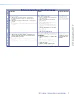
Turn on the input devices (DVD players, VCRs, PCs, and other sources), output devices
(display screens, projectors), the IPL Pro control processor, and the PC and touchpanel.
Touch a configured button on the touchpanel.
If an input or output AV device cannot be remotely controlled (does not respond as
expected), check the following:
Power Connections
•
Ensure that all devices are plugged in.
•
Make sure that each device is receiving power. The IPL front panel power LED lights if
the device is receiving power.
Data Connections
1.
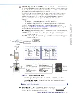
Check the cabling connections and make adjustments as needed. The Link LEDs on
the IPL and on the touchpanel or PC should be lit solid green if a network connection
is detected. If these LEDs are not lit, either the cable is faulty or not plugged in, or
the wrong type of cable is being used (see
LAN/PoE (IP) connectors and LEDs
on
page 14).
2.
Try to “ping” the unit by entering
ping 192.168.254.250
at the command prompt,
or use the IP or web address provided to you by your system administrator. If you get
no response:
•
Make sure your unit is using the appropriate subnet mask (check with your system
administrator).
•
Make sure your PC and network do not have a software firewall program that might
block the IP address of the IPL unit.
3.
If contact is established with the unit, but the IPL web pages cannot be accessed by
your web browser, verify (via an Internet network options or preferences menu) that
your web browser is configured for direct network connection and is not set up to use a
proxy server.
Device Control Connections and Configuration
•
Verify that ports are wired correctly and that ground (earthing) wires are connected to
the proper pins on the control processor and, if applicable, on the controlled device.
•
Verify that the appropriate drivers were used while creating the GC Professional or
GC Plus configuration file and that the correct commands and signal types (RS-232,
Ethernet) are associated with the appropriate ports on the IPL and on the other devices.
If you are still experiencing problems, call the
Extron S3 Sales & Technical Support
Hotline
or the
Extron S3 Control Systems Support Hotline
(1.800.633.9877).
•
Text to add once models with IR ports are added:
•
Ensure that each IR emitter head is placed adjacent
to or directly over the IR pickup window on the
controlled device.
•
IR,
•
Text to add once models with these ports are added:
•
For digital input and output connections, verify whether
the application requires the +5 VDC pull-up resistor within
the IPCP for TTL circuits and use the software to check
whether it is selected within the configuration.
•
Verify that input current at any digital input or output port
does not exceed 250 mA.
PRELIMINARY


