


IN1404 User’s Manual
9
Video Audio
Input Output
Advanced
Brightness
Bass
Signal
Format
Resolution
Factory Reset
Contrast
Treble
Aspect Ratio
Refresh Rate
User Memory
RGB Gain
3
Balance
Auto
Switching
Size
Baud
Rate
Color Saturation
2
Reset Audio
Input Labels
Position
Delimiters
Hue
2
Horiz. Tracking
Sync Format
Reset RS-232
Sharpness
2
Reset Audio
Phase
Blue Screen
System Info
Gamma
2
Yes
Advanced
Reset
Output
Noise Filter
2
No
Reset
Input
Factory Reset
Comp/Trap
2
Resolution
Yes
Reset Video
Input #
Signal Format
640 x 480
No
Composite
Input 1
800 x 600
RGB Gain
3
S-video Input
2
852 x 480
User Memory
Red
Component
Interlaced
4
Input 3
1024 x 768
Save
Green Component
Input
4 1152
x
864 Recall
Blue RGBS
4
1280
x
720
Reset
RGsB
4
Aspect Ratio
1280
x
1024
Comb/Trap
2
RGBHVS
Passive
4
Standard 1365
x
768
Baud Rate
Comb Filter On
RGsB Passive
4
Anamorphic
1365
x
1024 1200
Trap Filter On
Wide
Screen
2400
Wider
Screen
Refresh Rate
5
4800
Reset Video
Tomarama
56 / 60 / 65 Hz
9600
Yes
72 / 75 Hz
19200
No
Auto Switching
85 / 96 Hz
38400
On / Off
100 Hz
57600
120
Hz
Input Labels
Delimiters
On / Off
Size
Parenthesis
Momentary
H-Size
Brackets
Reset
label
V-Size
Slashes
Less
&
Greater
Advanced Features
(under
Input
menu)
Horizontal
Tracking
3
Position
Signs
!#
Active Area
Very
Fast
H-Position
Active
Pixels
Fast
V-Position
Reset RS-232
Active
Lines
Normal
Yes
Blanking
Slow
Sync Format
No
H-Blanking
RGBHV--
V-Blanking
Advanced
RGBHV++
System Info
Scan Type
3
Active Area
RGBS A
Input #
Interlaced
Blanking
RGBS B
Signal Format
Swap Fields
Total Pixels3
RGsB A
Input Horiz.
Invert Sync
Scan Type
RGsB B
Input Vert.
Input Mode
Input Mode
Output Size
Auto
Detect
Blue Screen
Output
Horiz.
Lockout
Changes
Reset Input
On/Off
Output
Vert.
User Defined
Yes / No
Sync Format
Redetect
Now
Reset Output
Version
Yes/No
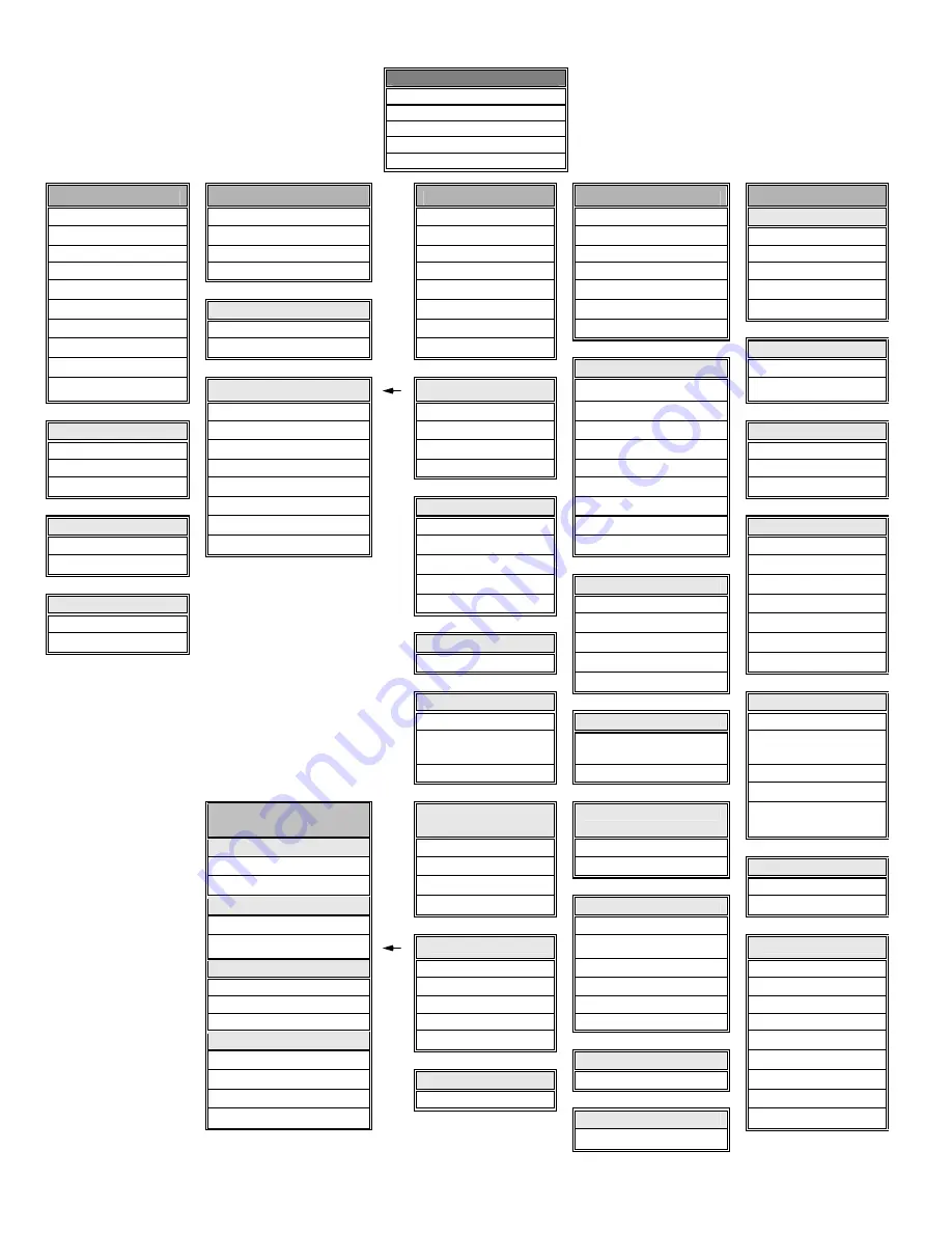
Main Menu
Video
Audio
Input
Output
Advanced
IN1404 on-screen display
menu system


