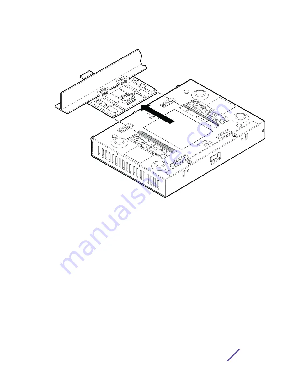
5 Slide the T-bar ceiling mount bracket base into the back of the access point. The locking tab fits into
a groove in the outside of the AP.
Figure 8: Attaching the AP3915e unit onto the WS-MBI-DCFLUSH bracket
6 Hold the AP and rock it back and forth to ensure that it is securely mounted.
7 Attach the Ethernet cable’s RJ45 connector to the LAN1/GE1 port and place the ceiling tile back in
place.
Mounting the AP using the WS-MBI-DCMTR01 Bracket
The optional WS-MBI-DCMTR01 (#30518) bracket can also be used for T-bar installations without the
mounting bracket.
Pre-Installation checklist:
•
T-bar width must be 9/16” (15mm), 15/16” (24mm), 1.5” (38mm).
•
T-bar minimum base thickness: N/A; must be structurally sound.
•
T-bar maximum base thickness is 0.118” (3mm).
•
T-bar can have a maximum protrusion of 0.625” (15.8mm).
•
Maximum protrusion of the ceiling tile can be 0.625” (15.8mm).
1 Remove the ceiling panels around the drop ceiling T-bar rail.
2 Open the movable sliding part of the T-bar to give the stationary and slider T-bar more space.
3 Hook the stationary end of the T-bar bracket onto the T-bar.
Installation Process
ExtremeWireless™ AP3915e FCC/ROW Install Guide
17


