


ASSEMBLY MANUAL: Glasair SII / III
the “Y” pushrod into each of the plastic tubes, then push the rod into the fuselage;
the plastic tubes will guide the ends of the “Y” out the slots in the fuselage.
Elevator Pushrod Installed
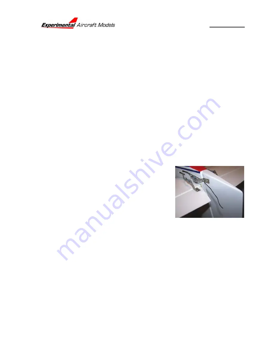
14. Next install the Rudder Pushrod. You can use the plastic tube as a guide as you
did with the elevator pushrod, but frankly the rudder pushrod is simple enough to
just reach into the fuselage and poke around until you find the lower pushrod exit
on the starboard side of the fuselage.
Rudder Pushrod Installed
15. Next install the control horns. For the rudder, start by installing the horn on the
clevis on the rudder pushrod. This will align it at the correct height. Next slide the
base of the horn on the fore and aft on the rudder until the pushrod holes align with
the hinge line. Put a pin in one hole to locate it while you drill the other. Then put a
screw into the hole you just drill, remove the pin and drill the second hole.
Rudder Horn Installed
16. When using a double ended pushrod it is imperative that the elevator horns be
installed correctly and exactly opposite each other in order to assure that the
elevators always move in complete unison. Start by
loosely taping the FRONT of the pushrod to the
center of the servo mounting bar up front. Better
still; use a small piece of plastic over the wire so the
pushrod will still move. Install an elevator horn on
each clevis. Use some clamps or tape to hold both
elevators in the neutral position. Position the horns
an equal distance from the centerline of the
fuselage, i.e., offset from the edge of the elevator by
12-16mm (
1
/
2
” to
5
/
8
”) from the edge of the elevator. Use a pin in one of the horn
mounting holes to hold its position on the elevator then drill.
Rudder Horn Installed
Align the horn and link with the servo arm, align the horn as far forward as possible
WITHOUT overhanging the beveled edge, then drill a 2mm (
5
/
64
”) hole for each control
horn screw. NOTE: in order to prevent drilling through the control surface use a drill
stop. The middle picture shows a wheel collar affixed over the drill bit to assure that
the hole is drilled just as deep as needed for the screw.
With the rear-most screws, you might want to cut off the excess screw length and file
off the burr
Page 23


