Experimental Aircraft Models Glasair III Assembly Manual Download Page 1


“Enhancing the Homebuilt Experience”


Radio Control Scale Model


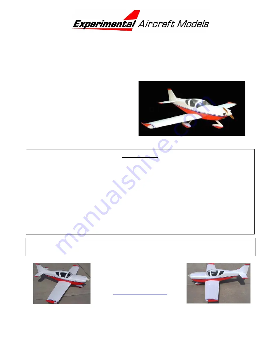
Glasair SII / Glasair III


Scale:  1= 3.5 (28% Full Size) 
Wingspan: 80” (2032 mm)  
Wing Area: 1024 in

2

 (66.1 dm

2

Flying Weight: 12 lbs (5.04 kg) 
Wing Loading: 27 oz/ft

2


Length: 70” (1778 mm)  
Radio: 5 Channels with 7 servos  
Engines:   1.08 – 1.2 cu in 2 Cycle  
 

1.20 – 1.4 cu in 4 Cycle 


Please read this manual thoroughly before starting assembly.  It includes critical assembly 
instructions and warnings in regards to the safe and enjoyable use of this scale aircraft model. 

WARRANTY 

Experimental Aircraft Models, LLC (EAM) guarantees this kit to be free from defects in material 
and workmanship.  The warranty does not cover individual parts damaged by modification or 
abuse.  In no case will EAM’s responsibility or liability exceed the original purchase price of the 
kit.  EAM reserves the right to change or modify this warranty at any time. 
 
EAM assumes or accepts no liability for the manner in which this model aircraft is used by the 
user, in any condition of assembly.  By the act of purchasing this kit, the purchaser and any 
subsequent user accepts full responsibility and all resulting liability. 
 

If the purchaser is not willing to accept the above liability associated with the use of this 
model aircraft, the purchaser is advised to return this kit immediately to the source from 
where it was obtained. 


Experimental Aircraft Models LLC 

1224 Amber Dr. 

Thunder Bay, Ontario  

Canada, P7B 6H7 

www.rchomebuilts.com


Summary of Contents for Glasair III

Page 1: ...nship The warranty does not cover individual parts damaged by modification or abuse In no case will EAM s responsibility or liability exceed the original purchase price of the kit EAM reserves the right to change or modify this warranty at any time EAM assumes or accepts no liability for the manner in which this model aircraft is used by the user in any condition of assembly By the act of purchasi...

Page 2: ...s model We control the entire process of the model construction starting with the direct import of balsa logs from Ecuador to hand carving the fiberglass plugs and lay up of the fiberglass components The canopy molds are also hand carved and the vacuum forming is all done in house You get to make similar choices as the Glasair homebuilder type and size of engine fixed gear or retracts as well as m...

Page 3: ...u need contact us One of the first things to determine is exactly WHAT version of the Glasair are you going to build Just as the homebuilder customizes their personal aircraft your Experimental Aircraft Models kit enables you to choose between the Fixed Gear or Retract equipped Glasairs The Glasair S II or Super II line offers the RG Retractable Gear the FT fixed tricycle gear There is also the TD...

Page 4: ...y slippery finish that that resists adhesive bonding It must be removed from any joint to be glued Failure to remove the covering from glue zones will result in failure of the affected glue joint and likely damage or destroy your model The recommended engines are a 1 08 1 20 two stroke or 1 20 1 40 four stroke Experimental Aircraft Models discourages the use engines larger than this range The Glas...

Page 5: ...ir could be flown with a 4 channel radio with 5 servos with fixed gear and the flaps locked in the neutral position but where s the fun it that Additional components you may need from the hobby shop CA Adhesive Thin CA Adhesive Medium Epoxy 30 minute cure Silicone Seal Adhesive Heavy Duty Servo Lead Extensions 2 450mm 18 for ailerons with JR Plug recommended Heavy Duty Servo Lead Extensions 2 150m...

Page 6: ... pointing up so the epoxy can flow down into the hole Put a second drop in each pocket if needed One at a time push the hinge points into their pockets if the epoxy purges out of the hole then back out the hinge point wipe the excess epoxy off then reinsert it Inspect each hinge to see that it is square to the surface Then pivot the hinge and check again to see it is square Press the surface up ag...

Page 7: ...wo to the other direction Rough up the inside surface of the servo cover with some sandpaper to promote better adhesion of the servo mounting blocks Servo Covers Sorted Prepped 1 2 3 4 2 Position the servo by centering the servo output arm in the slot then use a spring clamp to hold it in position OPTIONAL put a dab of silicone seal on the servo before clamping the servo down it will help retain t...

Page 8: ... then if needed remove the servo arm from one servo and reinstall it so it matches the position of the other servo Port Flap Servo Extension Installed Retained Starboard Flap Servo Extension Installed Retained Port Aileron Extension Installed Retained Starboard Aileron Extension Installed Retained All Servos Harnesses Checked for Operation 5 As shipped the servo bays are covered over with Oracover...

Page 9: ...ssemble the clevis onto the aileron flap links and install each link onto a control horn Align the horn and link with the servo arm align the horn as far forward as possible WITHOUT overhanging the beveled edge then drill a 2mm 5 64 hole for each control horn screw NOTE in order to prevent drilling through the control surface use a drill stop The middle picture shows a wheel collar affixed over th...

Page 10: ...he Aileron Rudder or Elevator channel and then set both servo arms to neutral When you plug the harness back into the flap channel you should see the servos working together throughout the range of flap settings Port Flap Servo Linkage Starboard Flap Servo Linkage 11 Before installing the installing the servo covers for the last time give each screw hole a drop of thin CA and when dry drill it aga...

Page 11: ...a little more straight forward Certain details of the engine installation will vary depending on whether you use a 2 stroke or 4 stroke engine We will cover both installations noting any peculiarities encountered 1 First step in the fuselage assembly is to remove the canopy hatch Near the back of the cabin you will find a slightly larger screw than the canopy screws lower on the fuselage than the ...

Page 12: ...ound the perimeter so it will push back over the firewall bulkhead The suggestion made and shown here is to ADD some ramps fabricated out of scrap wood at the 4 corners of the firewall that will help guide the cowl into position These are OPTIONAL but we found that they help us align the cowl Corner Ramps Optional x 4 installed 4 Locate all the tank hardware The tank is supplied with a plastic clu...

Page 13: ...eck opening and will likely interfere with the fuel tank tube The simple way out is to push the fuel tank back far enough to clear the mount However if you want to keep the tank as far forward as possible thus minimizing the fuel draw you will have to grind a clearance notch into the lower mount Half moon shaped clearance notch ground into lower mount Engine Mount Cleared 7 Remove the tank With th...

Page 14: ...rewall to drive washer is 5 81 5 87 147 5 149 mm Firewall to Drive Washer Target Dimension ________ and Actual ________ 10 When the engine position has been set spot mark the location of the engine mounting holes on the mounts The engine mount can be drilled either in place or the mounts can be removed and set up in a Drill Press Vise for drilling Drill the mounts for the 3mm x 30 mm or 6 32 x 1 2...

Page 15: ...nts are the same With a side mounted engine you will want to use a Pitts style muffler with the engine and muffler installed use the paper template method described in steps 2 3 above to locate the exhaust pipes Remove the muffler install the cowl and mark the exhaust tube exit positions This is also a step where the old adage to measure twice before cutting once will come into play Use tin snips ...

Page 16: ...nce Thus we will install these features to improve accessibility 1 The Glasair has a very large cowl that prevents direct access to the fuel filler so we will install a remote fuel filler Shown here is a Great Planes Easy Fueler Valve similar products also available from other sources shown installed on a plywood mount epoxied to the upper starboard side of the firewall The valve is positioned so ...

Page 17: ... the cowl and centered in its hole Fuel Filler Hole Cut In Cowl 4 No matter whether you install a 2 stroke or a 4 stroke engine with a side mounted engine access to the glow plug will be restricted While it is possible to use one of those long stemmed glow lighters to reach through a unsightly hole in the cowl to the glow plug we think a far better solution is a remote igniter located for access d...

Page 18: ...rward fuselage behind the firewall too Front End Painting Completed FUSELAGE TAIL ASSEMBLY A note about rudder and elevator pushrods The hardware shown above is supplied with the kit and is perfectly adequate for controlling your Glasair However as mentioned in the introductory comments if you intend to fly your Glasair at an IMAA event they will insist that you have 3mm or 4 40 sized control hard...

Page 19: ...imply needs to be about 650mm 25 6 measured from pin to pin on the clevis The pushrod shown also had some small Z bends to improve the fit there is no way to predict exactly what if any bends will re required just make sure the pushrod slides freely without interfering with the elevator rod final adjustments are made with the servo arm and rudder centered Rudder Pushrod Completed 3 Follow along wi...

Page 20: ...ng them to JUST the movable surfaces first Check all of the hinge pockets and clean up any execss covering ot other obstrction using a modeling knife Epoxy the hinge points into just these surfaces After the epoxy cures check the hinges for free motion chip away any excess epoxy and set these aside until they are needed again Hinges Epoxied into both Elevators To Rudder 7 Next sequence is to align...

Page 21: ... yet to be removed Covering Removed 10 Install the horizontal stab using 30 minute epoxy and CA Begin by applying a wet but not too globby coating of epoxy inside the top of fuselage the top block that contacts the stab Next apply a wet coat to the top of the stab not the bottom Carefully slip the stab to just before the epoxied area Lay a bead of epoxy on the previously wetted stab next to where ...

Page 22: ...e preferably overnight When cured wiggle each control surface and inspect EVERY hinge for signs of globs of epoxy that could be interfering with free motion of the control surface Elevators Rudder Installed 12 The last tail piece to install is the dorsal fin The Glasair has a relatively short tail the extra side area afforded by the dorsal improves directional stability do not leave it in the box ...

Page 23: ...hat the elevator horns be installed correctly and exactly opposite each other in order to assure that the elevators always move in complete unison Start by loosely taping the FRONT of the pushrod to the center of the servo mounting bar up front Better still use a small piece of plastic over the wire so the pushrod will still move Install an elevator horn on each clevis Use some clamps or tape to h...

Page 24: ...o hold it in position Allow enough clearance for the wheel to spin freely Wheel Centered Secured Metal Brackets Shim 5mm Spinner sleeve 3 Fit on of the metal brackets over the wire and onto the fairing near the top Drill the two 1 5mm 1 16 holes into the fairing where the bracket goes and install the bracket screws Repeat for the second bracket to be located somewhere midway along the wire and fai...

Page 25: ...a installed with silcone seal thus removable if the retractable gear is ever used Retractable Wheel Clearance Notch Sealed 6 Install the Nose gear pivot block with its wood spacer onto the firewall using the 3mm bolts provided Nose Gear Block Installed 7 The main gear assembly begins with installing the wheels and wheel pants onto the main gear Sort out the two 4mm x 40mm shoulder bolts 6 washers ...

Page 26: ...he center of the fuselage Some compromise versus perfection must be tolerated but can be minimized by mounting the elevator servo in the center bay of the servo tray Rudder Servo Rudder Pushrod to Aft Nose Gear Steering Pull Pull Cables Forward Elevator Servo Y Pushrod to Aft Throttle Servo Pushrod to Forward The throttle servo go in on the side that gives best access to the throttle arm in this c...

Page 27: ...p the ferrule over the cable slip the cable through the brass coupler an back through the ferrule but DO NOT CRIMP YET Repeat the process for the other cable getting it ready but stopping short of crimping it With the servo centered take you best shot at centering the nose wheel then crimp the ferrules Before you fly take the Glasair out on the driveway or other smooth surface and roll it back an ...

Page 28: ...harging jack as shown in the picture set below This particular switch used was actually slightly smaller than the pre cut hole so the first picture shows how to fill in part of the hole to fit the switch Note the covering has already been cut as a prelude to sealing the edges middle picture and finally installing the switch Switch Installed 7 Before installing the receiver make sure all the servo ...

Page 29: ...rudder each direction from center 10mm 16mm 3 8 5 8 Ailerons measured at the wing tip end each side of center 10mm 16mm 3 8 5 8 Flaps measured at the trailing edge from top of flap to top of wing 7 8 22mm Try using about 7mm 10mm 1 4 to 3 8 for Takeoff and up to full deflection for landing THE FLAPS WILL SLOW THE BIRD DOWN be ready to keep some throttle on FINAL ASSEMBLY 1 WEIGHT AND BALANCE This ...

Page 30: ...l surfaces move freely Check that control surfaces are at the same relative angles i e in line with the flying surface to which they are attached Check that all control horns are firmly attached Check that all control surfaces are firmly hinged by tugging on them Put some fuel in the tank and make sure the plumbing is correct Check correct operation of control surfaces with your radio that left is...

Reviews: