Violet Wire - (Positive Door Trigger):
The Violet wire is identical to
the Green Door Trigger wire, with the sole exception that it is an open door input
to the control module for vehicles having Positive 12 volt door pin switches.
Green Wire - (Negative Door Trigger):
The Green wire is an "open
door" input to the control module for vehicles having Negative switching door pin
switches. This wire is most commonly connected to the vehicle interior light
system.
CONNECTION:
Connect the Green wire to a wire in the vehicle that is
common to all the door pin switches; the correct wire in this type of interior or dome
light/door jamb pin switch system will have no voltage present and will also show
chassis ground when the doors are opened, and up to 12 volts when the doors are
closed.
Page - 11
12
12
12
12
12
12
12
1
1
1
1
1
1
1
12
12
12
12
12
12
1
1
1
1
1
1
1
1
1
1
1
1
1
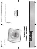
Passenger
Pin
Switch
(+)12 Volts
Driver
Pin
Switch
The Driver Pin Switch will often have
an extra wire that activates the “ignition
key in switch” warning chime. This
circuit will activate the security system,
but only from the driver's door, and is
the incorrect trigger wire >
123456789012
123456789012
123456789012
123456789012
123456789012
123456789012
123456789012
123456789012
123456789012
123456789012
123456789012
123456789012
123456789012
123456789012
Interior Light
Typical Negative Switching Interior Light System
This is the
correct "trigger”
wire - connection
may be made at
any point
)
1
1
1
1
1
1
1
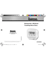
Driver
Pin
Switch
1234567890123
1234567890123
1234567890123
1234567890123
1234567890123
1234567890123
1234567890123
1234567890123
1234567890123
1234567890123
1234567890123
1234567890123
1234567890123
1234567890123
To Chassis
Ground
Interior
Light
To Constant
12 Volt
Note: The Driver Pin Switch
will often have an extra wire;
this circuit will activate the secu-
rity system, but only from the
driver's door. This is the incor-
rect activation wire >
Passenger
Pin
Switch
This is
the correct
“trigger” wire -
connection may
be made at any
point
Typical Positive Switching Interior Light System
)
time that the ignition switch is turned on. An exception to this would be if feature
#8 is turned on, and a door being open when the ignition switch is turned on. The
following feature #7 controls the automatic unlocking operations, and feature #8
provides for an override of this automatic locking if a door is open when the ignition
is turned on.
Feature #8 Open Door Bypass of Ignition Locking
Factory Default Setting
On (
press
“arm/lock” button to program
)
Option:
Off (
press
“disarm/unlock” button to program
)
This feature cancels the automatic locking or
unlocking of the vehicle’s doors
should one of the doors be open when the ignition switch is turned on or off.
Feature #7 Doors Unlock With Ignition Off
Factory Default Setting
On (all doors will unlock)*
(
press
“
III
” button to program
)
Options:
Off
(
press
“arm/lock” button to program
)
Driver’s Door Only*
(
press
“disarm/unlock” button to program
)
All Doors Except Driver’s Door*
(
press
“
II
” button to program
)
Similar to the previous locking feature, except this feature controls the unlock
operations when the ignition is turned off, and it has more options because of the
multiple unlocking outputs of the DLS port.
*Multiple unlock outputs offer the capability of unlocking only the driver’s
door when the system is disarmed (Driver Door Priority Unlocking), and then the
option of unlocking all doors with a second press of the “disarm/unlock” button.
The driver’s door unlocking differently from the other doors must be config-
ured when the system is installed!
If the system is installed without the Driver’s Door Priority Unlocking interface,
this feature unlocks all of the doors when the ignition switch is turned off.
If Driver’s Door Priority Unlocking is installed, this feature can control only the
driver’s door unlocking when the ignition is turned, all doors unlocking, or all doors
except the driver’s. The following feature provides for an override of this automatic
unlocking if a door is open when the ignition is turned off.
Feature #9 Confirmation Chirps
Factory Default Setting
On
(
press
“arm/lock” button to program
)
Options:
Off
(
press
“disarm/unlock” button to program
)
Chirps Excepting Valet Mode
(
press
“
II
” button to program
)
Chirps in Valet Mode Only
(
press
“
III
” button to program
)
This feature removes the system’s 1 arming and 2 disarming confirmation chirps.
Page - 26