Design and function
Transport and installation
099-005549-EW501
12.11.2018
21
• Unscrew and remove the coolant tank sealing cover.
• Check filter sieve insert for dirt, clean if necessary and reinsert into position.
• Top up coolant to the filter sieve insert, close sealing cover again.
If the cooling system is empty or only insufficiently filled with coolant, the coolant pump is
automatically switched off after approx. one minute (protection against destruction). At the same
time, the welding data display signals the lack of coolant or low coolant level.
• Reset the coolant error, fill coolant and repeat the operation.
The level of coolant must never fall below the “min” mark.
If there is less coolant in the coolant tank than the minimum required you may need to vent the
coolant circuit. In this case the welding machine will automatically shut down the coolant pump
and signal an error,
> see 7.2 chapter
.
5.1.6
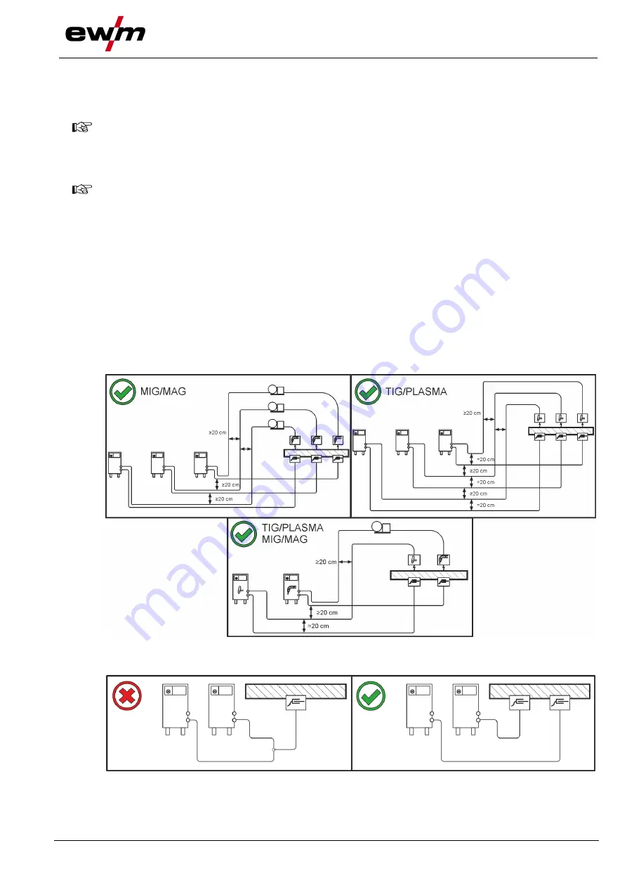
Notes on the installation of welding current leads
• Incorrectly installed welding current leads can cause faults in the arc (flickering).
• Lay the workpiece lead and hose package of power sources without HF igniter (MIG/MAG) for
as long and as close as possible in parallel.
• Lay the workpiece lead and hose package of power sources with HF igniter (TIG) for as long as
possible in parallel with a distance of 20 cm to avoid HF sparkover.
• Always keep a distance of at least 20 cm to leads of other power sources to avoid interferences
• Always keep leads as short as possible! For optimum welding results max. 30 m (welding lead
+ intermediate hose p torch lead).
Figure 5-2
Use an individual welding lead to the workpiece for each welding machine!
Figure 5-3


