8
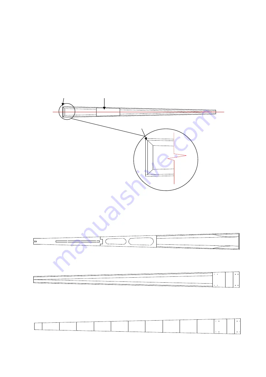
Glue the excess triangular fillet to the underside of F2 and dry fit between the Fuselage sides, ensure that F1
fits in the 3mm (1/8”) recess left at the front. If you are building the electric version carefully drill holes at the
top and the bottom of the former to allow air to enter the Fuselage for cooling.
F1 should be placed with the pre cut hole set towards the bottom of the Fuselage, once glued in place
chamfer the top and bottom to follow the Fuselage sides.
With F1 and F2 in place the Fuselage sides should taper back so that the triangular fillet at the rear just
touches. Once satisfied that the part fits correctly glue in place using epoxy. We have found this easier by
gluing F2 to one side of the Fuselage first and allowing to dry before offering the other side and inserting F1.
Ensure that F1 is 90° to the centre line of the Fuselage.
We have shown standard servos fitted in the Fuselage, but recommend that you use a good quality
mini/micro servo to reduce weight. Ensure the mini/micro servo is of the same or better specification as a
standard servo.
Once the epoxy has set, the top rear deck (Part 22) to the Fuselage, ensuring the rear Fuselage remains
square and the cut out for the Fin remains along the Fuselage centre line.
With epoxy glue the front ply (Part 26), centre balsa (Part 2) and rear ply (Part 28) undercarriage plates into
position.
With the supplied the sheet of 3mm (1/8”) balsa plank the front top deck of the Fuselage. If you are building
the
glow version
continue to plank the whole of the bottom. The planking grain should run from side to side
to provide maximum strength.
CL
F1
F2
F1 set flush with front of
fuselage, triangular fillet set
back 3mm to allow this
.
3mm


