11
11
11
11
The last display on the screen has a “*” sign in the top-middle. The sign will replace
the “*” in the display when sequence occurs.
Note:
Sequence is invalid when the multi-screen display is showing all cameras.
Temperature indication.
This shows if the hard drive’s temperature is overheated.
Overheat temperature is determined in
HDD TEMPERATURE
of
WARNING
SETUP MENU
.
Fan fail indication.
This shows when the fan fails to work normally. If you get this warning, contact
technical support for assistance.
3
.
Select sign:
You can assign a camera to a display by
pressing
SELECT
key in live
mode. Dial
Jog
to move the select sign to the display you would like to change camera,
and then press channel key on the front panel to choose that channel. Press
SELECT
again to exit from this mode.
4
.
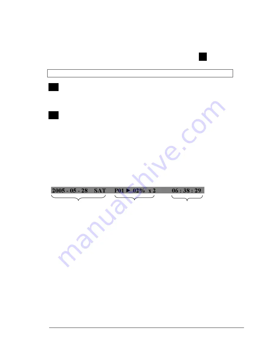
Play status bar:
The play status bar appears in play back mode if you enable a
status bar on the screen (Please see
DISPLAY,
8
th
item of
Front Panel Keypads
).
There are three parts that will be shown:
play date
,
play status
, and
play time
.
1.
Play date
The date on which the video was recorded.
2.
Play status
“
PAUSE
”, when the video playback is paused.
“
P## >
” means normal play speed on the displayed disk number;
“
P## <
“ means normal reverse play speed on the displayed disk number;
“
>> x N
” means N time fast play speed;
“
<< x N
” means N time fast reverse play speed.
3.
Play time
The play time at which the video is recorded. The time format depends on the
time format setting in the
TIME/DATE SETUP MENU.
Play Date Play Status Play Time
S
T
F
Summary of Contents for EDVR16D1/250
Page 1: ...Instruction Manual 16 9 4 Channel Digital Video Recorder EDVR SERIES ...
Page 94: ...84 84 84 84 ...
Page 95: ...85 85 85 85 ...
Page 96: ...86 86 86 86 ...
Page 128: ...118 118 118 118 CAMERA setup menu RECORD setup menu ALARM setup menu ...
Page 131: ...121 121 121 121 SCHEDULE setup menu CONTROL setup menu ...
Page 133: ...123 123 123 123 AppendixA RemoteControl Appendix A ...
Page 137: ...127 127 127 127 AppendixC RJ45 RS485 PinAssignment Appendix C ...
Page 150: ...140 140 140 140 17 Format disc prepare your disc for file writing ...


