background image

Page | 5 


AP1004WRe Installation Guide 


Connecting AP 1004WRi 


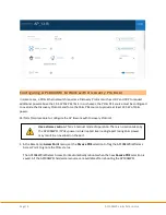
Perform this procedure to connect the AP1004WRi Wireless Access Point to the network. 

1.


For Access Points powered from a Network Switch with PoE+ capabilities, Attach the two 
cables directly to the Eth0 and ETH1 RJ45 receptacle on the back side of the AP1004WRi 
Wireless Access Point chassis. 


Locate Ethernet Ports 

Connect Primary Port 

Connect Secondary Port 

2.


For Access Points powered from the optional AC/DC Adapter, Attach the Power Connector 
first, then attach the Ethernet cables to the Eth0 and ETH1 RJ45 receptacle. 


Connect Power Adapter 

Connect Primary Port 

Connect Secondary Port 


3.


Connect the opposite ends of the Ethernet cables to a Ethernet Switch. If using Network 

power, Verify the network power source (PSE)  is configured to supply PoE+ power  (30 

Watts/Port) and supports 2-Event Classification, or the AC/DC Adapter is plugged into a AC 

Source.


When injectors or mid-span are used, connect the access point to the “Data + Power” port 

and the Ethernet Switch to the “Data” port of the injector or midspan.  


4.


Verify the PoE+ source is providing power and the Ethernet switch port has established link with both 
the ports. Note: Eth1  is normally disabled in the access point, so while it will link, no packets will be 
transferred unless the access point is configured to support link aggregation. 

Summary of Contents for AP1004WRi

Page 1: ...EVEREST Network Solutions INSTALLATION GUIDE AP1004WRi Wireless Access Point Model Number AP24I612 ...

Page 2: ...Release Number 1 4 ...

Page 3: ...Third Party Mounting System Installation 3 Connecting AP 1004WRi 5 Chapter 3 Configuring AP1004WRi 6 Logging into BaseCamp 6 Configuring AP 1004WRi 6 Configuring AP1004WRi to Work with Discovery Protocol 8 Chapter 4 AP1004WRi Coverage 9 AP1004WRi Radiation Pattern 9 Regulatory Declarations 11 Appendix Technical Specifications 16 Mechanical Specifications 16 Operational Requirements 16 Environmenta...

Page 4: ...ak surges caused by lightning Explosive Device Proximity Warning Do not operate network devices close to explosive merchandise or in explosive environments for example in the vicinity of a gas station Antenna Placement Warning Do not install any antenna near overhead power lines or other electric light or where the antenna can come into contact with such circuits Grounding Warning Protect your AP1...

Page 5: ... Dependencies The installation and configuration of AP1004WRi Wireless Access Point depends on the following components Access Controller BaseCamp Wireless Management System DHCP Server AP1004WRi Package Contents The AP1004WRi package consists of the following item One AP1004WRi Wireless Access Point Additional Item The following additional item is to be purchased separately Access Controller The ...

Page 6: ...ireless Access Point Top View Figure 2 AP1004WRi Wireless Access Point Bottom View Related Documentation AP1004WRe Installation Guide AP1004NRe Installation Guide AP1002We Installation Guide AP1002Oi Installation Guide Access Controller Installation Guide BaseCamp Wireless LAN Management System User Guide BaseCamp Wireless LAN Management System Quick Start Guide ...

Page 7: ...rizontal and vertical directions and are tapped with a M4 x 0 7 mm thread pattern to a depth of 10mm The AP1004WRi installation must be performed by certified technicians only and in compliance with all local state federal safety requirements and building codes Proper grounding and surge protectors may be required in some installations The network coverage depends on the location and position of t...

Page 8: ...Third party systems must be capable of safely supporting the AP1004WRi Wireless Access Point The exposed screw length exclusive of mounting bracket thickness and any washers or locking devices cannot exceed 10 mm so as to avoid any damage to the chassis Apply a drop of LocTite 243 threadlocker adhesive on each shoulder screw before inserting into the chassis to prevent loosening leakage andcorrosi...

Page 9: ...tacle Connect Power Adapter Connect Primary Port Connect Secondary Port 3 Connect the opposite ends of the Ethernet cables to a Ethernet Switch If using Network power Verify the network power source PSE is configured to supply PoE power 30 Watts Port and supports 2 Event Classification or the AC DC Adapter is plugged into a AC Source When injectors or mid span are used connect the access point to ...

Page 10: ...oE source must identify itself as PoE capable using the 2 event classification method For more information on configuring the AP1004WRi Wireless Access Points that are connected to POE sources that support a discovery protocol see Configuring AP1004WRi to Work With Discovery Protocol 2 Connect the AP1004WRi Access Point to a POE source Once powered up the AP1004WRi Access Point requests an IP addr...

Page 11: ... with a generic country code the Access Controller registers the AP1004WRi by overwriting the generic country code with the locked country code from the BaseCamp configuration After updating the country code the AP1004WRi is automatically rebooted allowing it to join the network If the AP1004WRi is set with a different country code the AP1004WRi is quarantined and not allowed to join the network 5...

Page 12: ... Perform this procedure to configure the AP to work with Discovery Protocol 1 In the BaseCamp Access Point menu set the Passive POE selection to flag the AP1004WRi Wireless Access Point to ignore the POE status The AP1004WRi Wireless Access Point automatically reboots when the new Passive POE selection is saved All the AP1004WRi hardware resources are available after rebooting the AP1004WRi Use ex...

Page 13: ...stem designers and integrators unparalleled flexibility in various deployment venues maximizing network capacity with fewer AP s and faster install times The 1004WRi leverages the combined power of four radios one 2 4 GHz 3x3 3 and three 5 GHz radios 4x4 4 with four spatial streams per radio for a total of 15 parallel streams In addition dual 2 5 Gbps Ethernet ports provide up to 5 Gbps of wired b...

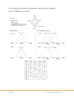
Page 14: ...Page 10 AP1004WRe Installation Guide The following figure shows fixed and reconfigurable coverage options for AP1004WRi Figure 5 AP1004WRi Coverage Options ...

Page 15: ...erent from that to which the receiver is connected Consult the dealer or an experienced radio TV technician for help This device complies with Part 15 of the FCC Rules Operation is subject to the following two conditions 1 This device may not cause harmful interference and 2 this device must accept any interference received including interference that may cause undesired operation This device and ...

Page 16: ...ent of the end product which integrates these modules Important Note FCC Radiation Exposure Statement This equipment complies with FCC radiation exposure limits set forth for an uncontrolled environment This equipmentshouldbe installedandoperated witha minimum distance of 20 cm between the radiator your body ...

Page 17: ...mum gain indicated for that type are strictly prohibited for use with this device Le présent émetteur radio 802 11bgn Scanning WiFi Radio Module IC 21218 TRM999DB and 802 11ac WiFi Radio Module IC 21218 TRM9995G a été approuvé par Industrie Canada pour fonctionner avec les types d antenne énumérés ci dessous et ayant un gain admissible maximal d antenne Les types d antenne non inclus dans cette li...

Page 18: ...650 5850 MHz and that these radars could cause interference and or damage to LE LAN devices Les utilisateurs être avisés que les utilisateurs de radars de haute puissance sont désignés utilisateurs principaux c à d qu ils ont la priorité pour les bandes 5250 5350 MHz et 5650 5850 MHz et que ces radars pourraient causer du brouillage et ou des dommages aux dispositifs LAN EL Important Note IC Radia...

Page 19: ...Page 15 AP1004WRe Installation Guide Japan Statement 5GHz band W52 W53 Indoor use only 電波法により 5 15 5 35 GHz 帯は屋内使用に限ります 5GHz band 5 15 5 35 GHz indoor use only VCCI Statement ...

Page 20: ...x 136 20 BTUs hr Per Port Power Max Available Input Power 42 5 56 Vdc 1 2 A 51 0 W 4P PoE source 42 5 56 Vdc 600 mA 25 5 W PoE source 37 56 Vdc 355 mA 12 95 W PoE source Optional DC Input 12Vdc 3333 mA 40 W Operating Condition Power Over Ethernet Limit1 AP Limit Worst Case 802 3at x 1 port1 Power Delivered over 2 Ethernet Pair 42 5 Vdc 588 mA 25 W 48 0 Vdc 521 mA 25 W 56 0 Vdc 466 mA 25 W 42 5 Vdc...

Page 21: ...Page 17 AP1004WRe Installation Guide 1 Some frequency bands may not be operational in power limitedoperations ...

Page 22: ...t Table 3 Environmental Requirements Condition Requirement Operating Temperature 0 C to 45 C 32 F to 113 F Storage temperature 40 C to 85 C 40 F to 185 F Humidity 5 to 95 non condensing Maximum elevation Operating Sea level 45 C 113 F 4 206 m 13 800 ft at 35 C 95 F Non operating 12 500 m 40 000 ft at 65 C 149 F Mean Time Between Failures MTBF 143 913 hours ...

Page 23: ...roving internal design operation function and or reliability Tembo Systems Inc reserves the right to make changes toproductsdescribed in this document without notice Tembo Systems Inc does not assume any liability that may occur due to the use or application of the product s described herein Document Number DOC 000023 000 Revision 01 Date May 2018 ...

Reviews: