background image

EVCO S.p.A. 


EVF 300 series | Installer manual ver. 1.3 | Code 144F300E134 

Page 54 of 62 

8. 

Do not operate for 60 s. 

9. 

Disconnect the EVKEY Micromatch connector from the device control module TTL serial port (upload will not be performed). 


For further information, see the documentation relative to EVKEY. 


18.1.4


Download the device settings 

Operate as follows to download the device settings: 

1. 

Cut the device power supply off. 

2. 

Insert the EVKEY Micromatch connector into the device control module TTL serial port. 

3. 

Connect the device power supply: the top part of the “UPPER” display will show “

Cln

” and the EVKEY signal LED will emit a 

green light. 

4. 

Hold the “TOP” key or the “FLOOR” key down for 4 s: the “UPPER” part of the display will show“

St

” flashing. 

5. 

Hold the “TOP” key or the “FLOOR” key down for 4 s: the top part of the “UPPER”display will show “

St

” on, the EVKEY signal 

LED will emit a red light and the configuration parameters download will be started. 


The download operation requires several seconds. If the operation is not completed successfully within this time period, i.e. 

if the EVKEY signalling LED does not stop emitting red light and emitting green light, the operation must be repeated. 

6. 

When downloading has been concluded, the display will restore normal viewing and the EVKEY signalling LED will emit a 

green light again. 

7. 

Disconnect the EVKEY Micromatch connector from the device control module TTL serial port. 


Operate as follows to exit the procedure before the operation is complete: 

8. 

Do not operate for 60 s. 

9. 

Disconnect the EVKEY Micromatch connector from the device control module TTL serial port (download will not be 

performed). 


For further information, see the documentation relative to EVKEY. 


18.2


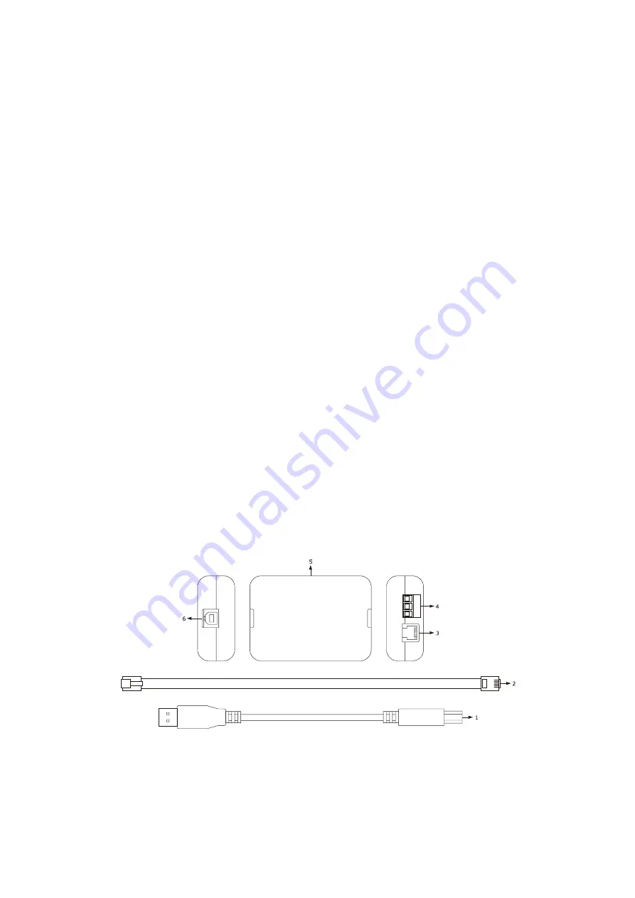
Optoisolated RS-485/USB serial interface EVIF20SUXI 

18.2.1


Preliminary notes 

EVIF20SUXI is an optoisolated RS-485/USB serial interface. 

The interface can be used to connect the device to the Parameters Manager set-up software system. 

The interface can be used on condition that the device is powered. 


18.2.2


Description 

The following drawing illustrates the aspect of the EVIF20SUXI. 


Summary of Contents for EVF 300 Series

Page 1: ...aller manual ver 1 3 Code 144F300E134 Page 1 of 62 EVF 300 series Controllers for electric bread and pizza ovens with touch keys in split version and which can be integrated into the unit Installer ma...

Page 2: ...fore use of the device and follow all recommendations keep this document with the device for future consultation Only use the device in the way described in this document do not use the same as a safe...

Page 3: ...ary notes 25 9 2 Memorisation of a program 25 9 3 Starting a program 26 9 4 Interruption of a program 26 10 WEEKLY PROGRAMMED SWITCH ON FUNCTION 27 10 1 Preliminary notes 27 10 2 Setting the switch on...

Page 4: ...e displays eleven touch keys and guarantees an IP65 protection rating for easy cleaning The controllers can independently manage the power supplied from the top and that supplied from the floor and th...

Page 5: ...et EVF318 EVF328 110 0 x 250 0 mm 4 330 x 24 999 cm L x H 2custom 3 4 digit displays with function icon number of keys touch key 11 11 protection rating IP65 IP65 Control module without cover EVF318 E...

Page 6: ...echanical relay technical compartment switch on off fan acoustic 8 A res 250 VAC electro mechanical relay 8 A res 250 VAC electro mechanical relay top 8 A res 250 VAC electro mechanical relay 12 V 30...

Page 7: ...grammed switch on function energy saving function quick heating function configuration parameters access password restoring the factory settings For further information see chapter 19 TECHNICAL DATA T...

Page 8: ...ing drawing illustrates the devices user interface dimensions these are expressed in mm in Installation is envisioned at the rear of the panel with biadhesive tape 2 2 Control module dimensions and in...

Page 9: ...equipment containing powerful magnets large diffusers etc areas affected by direct sunlight rain humidity excessive dust mechanical vibrations or shocks any metal parts in proximity of the control mo...

Page 10: ...configuration parameter u1 as follows extraction hood parameter u1 0 factory setting multifunction u1 1 The utility managed by the K5 digital output depends on the configuration parameter u11 as foll...

Page 11: ...minal board if the device has been taken from a cold to hot place humidity could condense inside wait about 1 hour before powering it make sure that the power supply voltage the frequency and the devi...

Page 12: ...tes the aspect of the devices user interface The following table illustrates the meaning of devices control module parts PART MEANING 1 communication port with the control module 2 termination resista...

Page 13: ...ormation see the next chapters 4 2 Description of the control module The following drawing illustrates the aspect of the devices control module The following table illustrates the meaning of devices c...

Page 14: ...EVCO S p A EVF 300 series Installer manual ver 1 3 Code 144F300E134 Page 14 of 62 10 TTL port 11 reserved 12 analogue inputs 13 reserved 14 RS 485 port and communication port with user interface...

Page 15: ...raph 14 5 Setting the configuration parametersthe configuration parameters The following table illustrates the meaning of the configuration parameters the parameters are listed with the order accordin...

Page 16: ...echnical compartment fan 1 switch on off 2 acoustic 0 Successively check that the remaining settings are appropriate see paragraph 14 7 List of configuration parameters 6 Connect to the electric mains...

Page 17: ...weekly programmed switch on has been activated the top part of the UPPER display will be off If the device is off the top part of the UPPER display will be off 6 4 2 The bottom part of the UPPER displ...

Page 18: ...rammed switch on function has been activated the bottom part of the LOWER display will be off If the device is off the bottom part of the LOWER display will be off 6 5 Silencing the buzzer Operate as...

Page 19: ...switched on and that no other procedure is in progress 2 Hold the STEAM GENERATOR key down for 1 s the TON LED will flash and the bottom part of the LOWER display will show the flashing tOn time value...

Page 20: ...n The time defined with the tOn parameter establishes the switch on duration of the injector and that defined with the tOF parameter that of switch off or for the entire duration that the key is press...

Page 21: ...is off with the delay established with parameter u12 from device switch off 7 5 2 Output switch on off only if parameter u11 is set at 1 The activity of the output switch on off depends mainly on the...

Page 22: ...meter r6 i e top set point r6 7 8 Chamber light 7 8 1 Preliminary notes Pressing and releasing the DOWN key will cause the chamber light to switch on until the key is pressed and released again or unt...

Page 23: ...r count will be re proposed if vice versa the duration of the cut off is longer than the time established with parameter r13 on restoring the power supply the cooking timer count will be interrupted F...

Page 24: ...1 Ensure that the device is switched on and that no other procedure is in progress 2 Press and release the START STOP key the TIMER LED will switch on and the bottom part of the UPPER display will sh...

Page 25: ...number of steam injections in cyclic mode is envisioned among the settings memorised in the program and on program start up the generator is off these will be switched on and the method of consent on...

Page 26: ...the program number will flash If no program is used the bottom part of the LOWER display will show flashing and the device displays will switch off 3 Press and release the UP or DOWN key within 15 s...

Page 27: ...ours minutes Operate as follows to set the switch on day 1 Make sure that parameter r12 is set at 1 that programs are used that the device is off and that no procedure is in progress 2 Hold the PROGRA...

Page 28: ...fore the operation is complete 13 Do not operate for 60 sec any changes will not be saved 10 3 Enabling the weekly programmed switch on function Operate as follows to activate the weekly programmed sw...

Page 29: ...modification will not be saved Operate as follows to exit the procedure before the operation is complete 5 Press and release the ON STAND BY key or do not operate for 15 s any modifications will not...

Page 30: ...nsure that the quick heating function is not in progress 2 Press and release the UP key the LED will switch on and the function will be activated until a key is pressed and released again or at maximu...

Page 31: ...WN key within 15 s to set the value of the day Operate as follows to set the hours 4 Press and release the CLOCK key while setting the day of the week the hours value will flash 5 Press and release th...

Page 32: ...fore the operation is complete 5 Do not operate for 15 sec any changes will be saved The working set point can also be set via parameter SP 14 3 Setting the top set point and the floor set point only...

Page 33: ...le to set the floor set point via parameter SP2 14 4 Setting the power distributed at the top and that distributed at the floor only if the CFG parameter is set at 0 Operate as follows to set the powe...

Page 34: ...ate for 15 sec any changes will be saved 14 5 Setting the configuration parameters Operate as follows to access the procedure 1 Make sure there is no cooking cycle or any procedure in progress 2 Hold...

Page 35: ...g cycle or any procedure in progress 2 Hold the UP and DOWN key for 4 s the top part of the UPPER display will show PA 3 Press and release the TOP key or the FLOOR key the LOWER part of the display wi...

Page 36: ...as follows to exit the procedure before the operation is complete 11 Hold the UP key and DOWN key down for 4 s before setting 1 i e before point 8 restore will not be performed Make sure that the man...

Page 37: ...AM MIN MAX U M INP 1 INP 2 WORKING SET POINT SP r1 r2 C F 1 150 not dis working set point see also r0 SP1 r1 r2 C F 1 not dis 150 top set point see also r0 SP2 r7 r8 C F 1 not dis 150 floor set point...

Page 38: ...type 0 thermocouple J 1 thermocouple K P2 0 1 0 0 temperature unit of measurement 2 0 C 1 F P4 0 2 2 2 steam injection activation consent mode 0 MANUAL steam injection will be allowed if the steam gen...

Page 39: ...RAM MIN MAX U M INP 1 INP 2 MAIN REGULATOR r0 1 99 C F 1 5 5 if CFG 0 work set point differential of SP if CFG 1 top set point differential of SP1 r1 0 r2 C F 1 50 50 if CFG 0 minimum work set point i...

Page 40: ...f injector switch on and tOF that of switch off or will cause steam injection for the entire duration the key is pressed t3 1 99 C F 1 5 5 SPS differential only if P4 2 t4 0 99 C F 1 50 50 temperature...

Page 41: ...80 80 if CFG 0 cycle time for switch on of the top output and the floor output see also Po1 and Po2 if CFG 1 cycle time for switch on of the top output and the floor output during the energy saving f...

Page 42: ...of the top above which the temperature alarm is activated code AH1 see also A3 8 A2 0 240 min 0 0 if CFG 0 temperature alarm display code AH1 if CFG 1 top temperature alarm delay code AH1 A3 0 2 0 0...

Page 43: ...type of door micro switch input contact 0 normally open input active with closed contact 1 normally closed input active with open contact i5 0 1 1 1 effect caused by the activation of the multifuncti...

Page 44: ...ed i16 0 1 0 0 type of electric absorption protection input contact 0 normally open input active with closed contact 1 normally closed input active with open contact PARAM MIN MAX U M INP 1 INP 2 DIGI...

Page 45: ...d that established with the SPS parameter if steam injection is not allowed the STEAM INJECTION key will flash 5 During the energy saving function the top output and the floor output are switched on a...

Page 46: ...d the activation mode of the steam injector will be AUTOMATIC PERSISTENT MANUAL TON switch on duration of the steam injector LED if it is on the value shown in the floor part of the LOWER display will...

Page 47: ...ributed at the floor LED if it is on the value shown in the top part of the LOWER display will be the value of the power distributed at the floor if it flashes setting of the power distributed at the...

Page 48: ...use temperature of the control module see parameter P7 when the cause of the alarm disappears press and release a key main consequences the device will be switched off the technical compartment fan wi...

Page 49: ...power supply the cooking timer count will be re proposed if vice versa the duration of the cut off is longer than the time established with parameter r13 on restoring the power supply the cooking tim...

Page 50: ...ept for the following alarms the use temperature alarm code Ht which requires a key to be pressed and released the power supply cut off alarm code PF which requires a key to be pressed and released th...

Page 51: ...respect to the top probe main consequences the floor probe will function as top probe and as floor probe Pr2 floor probe error solutions the same as the preceding case but with respect to the floor p...

Page 52: ...e main consequences if the alarm occurs when the device is on a cooking cycle cannot be started if the alarm occurs during a cooking cycle the cycle will be interrupted all outputs will be switched of...

Page 53: ...te as follows to upload the device settings 1 Cut the device power supply off 2 Insert the EVKEY Micromatch connector into the device control module TTL serial port 3 Connect the device power supply t...

Page 54: ...download operation requires several seconds If the operation is not completed successfully within this time period i e if the EVKEY signalling LED does not stop emitting red light and emitting green...

Page 55: ...VIF20SUXI 3 Connect the device control module clamp of the RS 485 port to the removable screw terminal clamp of the RS 485 port of EVIF20SUXI 4 Connect the device control module shield clamp of the RS...

Page 56: ...device power supply off 2 Disconnect the EVUSBREC01 power supply 3 Connect the device control module clamp of the RS 485 port to the EVUSBREC01 clamp of the RS 485 port 4 Connect the device control mo...

Page 57: ...on flat surface with spacers Protection rating user interface control module IP65 IP00 Connections user interface control module fixed screw terminal board control module removable screw terminal boa...

Page 58: ...ocouples thermocouple J type analogue inputs Type of sensor iron constantan Field of measurement from 99 to 8005 from 99 to 999 Resolution 1 C 1 F Protection none thermocouple K type analogue inputs T...

Page 59: ...8 outputs of which 6 electro mechanical relays and 2 solid state relays in the EVF328 model 1 x 8 A res output 250 VAC electro mechanical relay SPST type K1 for steam injection management 1 x 8 A res...

Page 60: ...r manual ver 1 3 Code 144F300E134 Page 60 of 62 Communication ports 2 ports 1 x TTL serial port for EVKEY programming 1 RS 48 serial port with MODBUS communication protocol for other EVCO products Sig...

Page 61: ...16 Code 144F300E134 This document is exclusive property of EVCO EVCO does not assume any liability regarding possible errors stated The customer manufacturer installer or final user assumes all liabil...

Page 62: ...EVCO S p A EVF 300 series Installer manual ver 1 3 Code 144F300E134 Page 62 of 62 EVCO S p A Via Mezzaterra 6 32036 Sedico Belluno ITALY Phone 39 0437 8422 Fax 39 0437 83648 info evco it www evco it...

Reviews: