background image


MM850592 ed. 01 - Mini MMX II 


2

INTRODUCTORY NOTE


This manual has been with all the information you need to install, operate and maintain the instrument. 
 
Eurotron has used the best care and efforts in preparing this book and believes the information in this 
publication are accurate. The Eurotron products are subjected to continuous improvement, in order to 
pursue the technological leadership; these improvements could require changes to the information of this 
book.  
 
Eurotron reserves the right to change such information without notice. 
 
Any maintenance operation must be carried out by qualified personnel only. Eurotron supplies instructions 
and operative procedures for any operation on the instrument. We recommend contacting our technicians 
for any support requirements. 
 
The instrument is fully tested in conformity with the directive n°89/336/CEE Electromagnetic Compatibility. 
Eurotron shall not be liable in any event, technical and publishing error or omissions, for any incidental and 
consequential damages, in connection with, or arising out of the use of this book. 
 
The operator must not use this equipment for any other purpose than that stated. 
This document is the property of Eurotron and may not be copied or otherwise reproduced, communicated 
in anyway to third parties, not stored in any Data Processing System without the express written authority of 
Eurotron Instruments S.p.A. 


All rights reserved 
Copyright © 2006  

Eurotron Instruments SpA 

Viale F.lli Casiraghi 409/413 
20099 Sesto S. Giovanni (MI) 
Tel. : +39-02 24 88 201 
FAX: +39-02 24 40 286 
Mail: [email protected] 


Summary of Contents for Mini MMX II

Page 1: ...Mini MMX II Professional Multimeter Multimetro Professionale Instruction Manual MM850592 ed 01 Manuale d uso MM850592 ed 01 ENGLISH ITALIANO 10A A mA V F C REL AC Hz DC AUTO Hz kM F C...

Page 2: ...on the instrument We recommend contacting our technicians for any support requirements The instrument is fully tested in conformity with the directive n 89 336 CEE Electromagnetic Compatibility Eurotr...

Page 3: ...expose the operator to a shock hazard Always recognize the meter voltage limits as stated on the front of the meter Never apply voltage or current to the meter that exceeds the specified maximum SAFET...

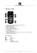
Page 4: ...5 Data Hold pushbutton 6 Relative pushbutton 7 Backlight pushbutton 8 Function switch 9 10A positive input jack for 10 uA mA input jack 11 Positive input jack for DC AC Voltage Hz duty cycle Ohms Diod...

Page 5: ...1604 IEC 6F22 Dimensions 182 H x 82 W x55 D mm Weight Approx 375g Accuracy is given at 18 C to 28 C 65 F to 83 F less than 70 RH DC Voltage Auto ranging Range Resolution Accuracy 400 0mV 0 1mV 0 5 of...

Page 6: ...of rdg 3 dgts Input Protection 600V dc or 600V ac rms Capacitance Auto ranging Range Resolution Accuracy 4 000 F 1pF 5 0 of rdg 0 5 F 40 00 F 10pF 5 0 of rdg 7 dgts 400 0 F 0 1 F 4 000 F 1 F 40 00 F 1...

Page 7: ...value exceeds the range you have selected Change to a higher range NOTE ON SOME LOW AC AND DC VOLTAGE RANGES WITH THE TEST LEADS NOT CONNECTED TO A DEVICE THE DISPLAY MAY SHOW A RANDOM CHANGING READI...

Page 8: ...e the reading in the display and the REL indicator will appear on the display 3 The display will now indicate the difference between the stored value and the measured value 4 Press the RELATIVE button...

Page 9: ...THE OUTLET BEFORE ASSUMING THAT NO VOLTAGE IS PRESENT CAUTION DO NOT MEASURE AC VOLTAGES IF A MOTOR ON THE CIRCUIT IS BEING SWITCHED ON OR OFF LARGE VOLTAGE SURGES MAY OCCUR THAT CAN DAMAGE THE METER...

Page 10: ...rent measurements up to 10A AC set the function switch to the A position and insert the red test lead banana plug into the 10A jack 5 Press the AC DC button until AC appears in the display 6 Remove po...

Page 11: ...lead banana plug into the negative jack COM and the red test lead banana plug into the positive jack 4 Touch the test probe tips to the diode or semiconductor junction you wish to test Note the meter...

Page 12: ...nge 2 Insert the Temperature Probe into the negative jack COM and the positive jack Temperature making sure to observe the correct polarity 3 Touch the Temperature Probe head to the part whose tempera...

Page 13: ...ES AND BATTERY TO MAKE SURE THAT THEY ARE STILL GOOD AND THAT THEY ARE PROPERLY INSERTED REPLACING THE FUSES WARNING TO AVOID ELECTRIC SHOCK DISCONNECT THE TEST LEADS FROM ANY SOURCE OF VOLTAGE BEFORE...

Page 14: ...AN AUTHORIZED RETURN AR NUMBER FROM EUROTRON S CUSTOMER SERVICE DEPARTMENT IN ORDER TO AVOID PROCESSING DELAYS Please include a copy of the original invoice or a small service charge may be applied T...

Page 15: ...di questo documento La Eurotron Instruments si riserva il diritto di modificarne il contenuto in qualsiasi momento e senza darne specifica notizia Eventuali interventi di manutenzione straordinaria do...

Page 16: ...pu danneggiare il multimetro ed esporre l operatore a scosse pericolose Tenere sempre presente i limiti operativi del multimetro come indicato sulla parte frontale dello strumento Non applicare mai t...

Page 17: ...ne Data Hold 6 Pulsante a pressione Misura Relativa 7 Pulsante a pressione per la retroilluminazione 8 Interruttore funzioni 9 Connettore d ingresso 10A positivo 10 Connettore d ingresso A mA 11 Ingre...

Page 18: ...2 Alimentazione una batteria 9V NEDA 1604 IEC 6F22 Dimensioni 182 A x 82 L x55 P mm Peso circa 375g L accuratezza dichiarata da 18 C a 28 C da 65 F a 83 F 70 di umidit relativa Tensione CC Auto range...

Page 19: ...1 1 0 val mis 2 d 40 00k 10 400 0k 100 4 000M 1k 1 2 val mis 2 d 40 00M 10k 2 0 val mis 3 d Protezione ingresso 600V CD o 600V CA RMS Capacit Auto range Range Risoluzione Accuratezza 4 000 F 1pF 5 0...

Page 20: ...uzione Accuratezza 20 C 760 C 1 C 4 F 1400 F 1 F 3 val mis 5 C 9 F Sensore termocoppia di tipo K Protezione da sovraccarico 600V CD o 600V CA RMS Test per Diodi Corrente di test Risoluzione Accuratezz...

Page 21: ...ente equivale al miglior modo per la maggior parte delle misure Per le misure che richiedono invece il cambiamento manuale del range operare come di seguito 1 Premere il pulsante RANGE L indicatore AU...

Page 22: ...ERARE POSSONO DANNEGGIARE LO STRUMENTO 1 Portare l interruttore funzioni nella posizione V DC apparir il simbolo mV sul display 2 Inserire il puntale a banana nero nel connettore negativo COM e quello...

Page 23: ...uare la misura di corrente 7 Collegare i puntali al circuito puntale nero al negativo del circuito 8 Dare alimentazione al circuito 9 Leggere il valore di corrente sul display Il display indicher anch...

Page 24: ...nettore positivo 3 Premere il pulsante finch il simbolo appare sul display 4 Toccare con la punta della sonda il circuito o il conduttore da misurare 5 Se la resistenza inferiore a circa 150 verr emes...

Page 25: ...her anche il corretto punto decimale e il simbolo Misura di temperatura ATTENZIONE PER EVITARE SCOSSE ELETTRICHE SCOLLEGARE ENTRAMBE LE SONDE DA QUALSIASI SORGENTE DI TENSIONE PRIMA DI EFFETTUARE LA M...

Page 26: ...issarlo con le due viti ATTENZIONE PER EVITARE SCOSSE ELETTRICHE NON UTILIZZARE LO STRUMENTO SE LO SPORTELLO DEL VANO BATTERIE NON RIPOSTO E FISSATO IN MODO SICURO NOTA SE LO STRUMENTO NON FUNZIONA CO...

Page 27: ...nts spa di cui sopra Qualora venisse rilevato un difetto la Eurotron Instruments spa a suo insindacabile giudizio decider se sostituire o riparare il prodotto stesso senza alcun addebito a carico del...

Reviews: