ALUDRA user manual
Issue A
36
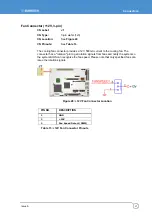
Backlight Inverter Connector
CN Label:
INVERTER1
CN Type:
5-pin wafer (1x5)
CN Location:
See Figure 24
CN Pinouts:
See
The backlight inverter connector provides the backlight on the LCD display connected to
the ALUDRA with +12V of power.
Figure 24: Panel Backlight Connector Pinout Locations
PIN NO. DESCRIPTION
1
LCD Backlight Control (PWM)
2 GND
3 +12V
4 GND
5 Backlight
Enable
Table 9: Panel Backlight Connector Pinouts
Summary of Contents for ALUDRA
Page 116: ...ALUDRA user manual Issue A 116 Appendix D Address Mapping I O Address Map ...
Page 117: ...Appendix D Address Mapping Issue A 117 Table IO Address Map ...
Page 118: ...ALUDRA user manual Issue A 118 IRQ Address Map Table IRQ Address Map ...
Page 119: ...Appendix D Address Mapping Issue A 119 Memory Address Map Table Memory Address Map ...
Page 123: ...www eurotech com ...


