ALUDRA user manual
Issue A
34
ATX Power Supply Enable Connector
CN Label:
J5
CN Type:
3-pin wafer (1x3)
CN Location:
See
CN Pinouts:
See
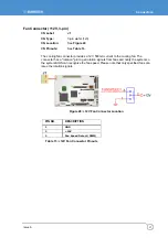
The ATX power supply enable connector enables the ALUDRA to be connected to an
ATX power supply. In default mode, the ALUDRA can only use an AT power supply. To
enable an ATX power supply the AT Power Select jumper must also be configured. See
, page
for more details.
Figure 22: ATX Power Supply Enable Connector Location
PIN NO.
DESCRIPTION
1 +5V
Standby
2 GND
3 PS_ON#
Table 7: ATX Power Supply Enable Connector Pinouts
Summary of Contents for ALUDRA
Page 116: ...ALUDRA user manual Issue A 116 Appendix D Address Mapping I O Address Map ...
Page 117: ...Appendix D Address Mapping Issue A 117 Table IO Address Map ...
Page 118: ...ALUDRA user manual Issue A 118 IRQ Address Map Table IRQ Address Map ...
Page 119: ...Appendix D Address Mapping Issue A 119 Memory Address Map Table Memory Address Map ...
Page 123: ...www eurotech com ...


