


25
2527245-02-01/22 (translation of the original operating instructions)
Operating Instructions
Safety System MGBS-P-L.-AP…
EN
11.10. Notes on operation with safe control systems
Observe the following requirements for connection to safe control systems:
Ì
Use a common power supply for the control system and the connected safety switches.
Ì
The device tolerates voltage interruptions on UB of up to 5 ms. Tap the supply voltage directly from the power supply unit. If
the power supply is connected to a terminal of a safe control system, this output must provide sufficient electrical current.
Ì
The safety outputs (FO1A and FO1B) can be connected to the safe inputs of a control system. Prerequisite: the input
must be suitable for pulsed safety signals (OSSD signals, e.g. from light grids). The control system must tolerate test
pulses on the input signals. This normally can be set up by parameter assignment in the control system. Observe the notes
of the control system manufacturer. For the pulse duration of your safety switch, please refer to chapter
Ì
The following applies to single-channel control of guard locking:
-The guard locking (IMM) and the control system must have the same ground.
Ì
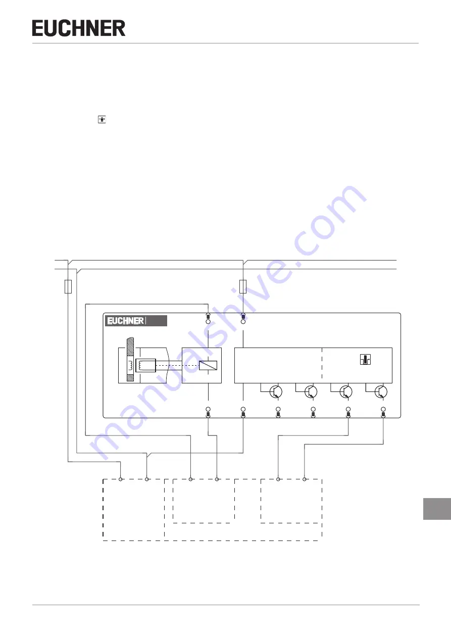
For dual-channel control of the solenoid voltage by safe outputs of a control system, the following points must be observed
):
-If possible, switch off the pulsing of the outputs in the control system.
-Pulses up to a length of max. 5 ms are tolerated.
A detailed example of connecting and setting the parameters of the control system is available for many devices at
www.euchner.com, in the area
Download/ Applications/MGBS
. The features of the respective device are dealt with there in
greater detail.
4/8 F-DI
PWR
Supply of
the control
4F-DO
Safety Outputs
Door
Monitoring
Read Head
Actuator
Monitoring Outputs
FO1B
4
OI
5
Diagnostic
-B1
UB
2
IMP
1
IMM
8
0 V
UB
7
OD
6
FO1A
3
MGBS
1
2
-F2
-X1
DI4
DI0
DC24V
M
-X1
DO..P
DO..M
1
2
-F1
24V DC
0 V
24V DC
0 V
Fig. 5:
Connection example for the connection to ET200