


13
2105267-10-08/20 (Translation of the original operating instructions)
Operating Instructions
Non-Contact Safety Switch CES-AH-C03-AE-LS
EN
CAUTION
Ì
A short circuit between the cables on the safety outputs LA and LB and another cable must be
prevented.
Ì
In certain circumstances, fault exclusion as per EN 13849-1, section 7.3, can be applied; see also
EN 13849-2, section D.5.2.
Ì
The CES-AH represents a subsystem as per EN 13849-1 and complies with PL d. To integrate the
switch in a category 3 structure, it is necessary to monitor the downstream load (the feedback
loop must be monitored).
Ì
This example shows only an excerpt that is relevant for connection of the CES AH system. The ex-
ample illustrated here does not show complete system planning. The user is responsible for safe
integration into the overall system.
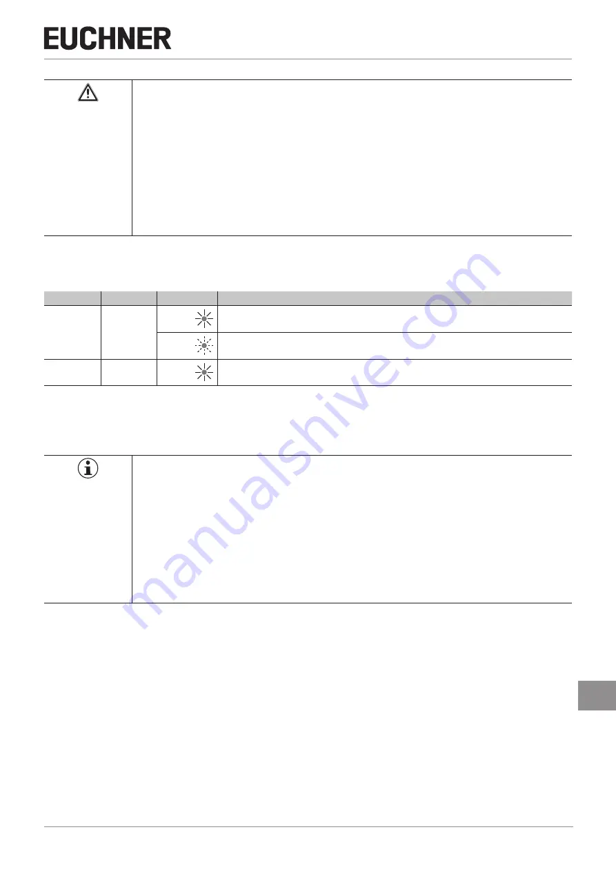
9. Setup
9.1. LED displays
LED
Color
State
Meaning
STATE
green
illumi-
nated
Normal operation
flashing
Teach-in operation or power-up
(for further signal function see status table)
DIA
red
illumi-
nated
- Internal electronics fault
- Fault at the inputs/outputs
9.2. Teach-in function for actuator
The actuator must be allocated to the safety switch using a teach-in function before the system forms a functional unit.
During a teach-in operation, the safety outputs are in high-resistance state, i.e. the system is in the safe state.
Important!
Ì
The safety switch disables the code of the preceding device if teach-in is carried out for a new
actuator. Teach-in is not possible again immediately for this device if a new teach-in operation is
carried out. The disabled code is deleted again in the safety switch only after a third code has
been taught.
Ì
The safety switch can be operated only with the last actuator taught-in.
Ì
If the switch detects an actuator that has already been taught when in teach-in standby state, this
state is ended immediately and the switch changes to normal state.
Ì
If the actuator to be taught-in is within the actuating range for less than 60 s, it will not be activat-
ed and the most recently taught-in actuator will remain saved.
9.2.1. Carrying out teach-in for a new actuator
1. Apply operating voltage to the safety switch.
¨
The green LED flashes quickly (approx. 10 Hz).
A self-test is performed during this time (approx. 3 s). After this, the LED flashes cyclically three times and signals that
it is in standby state for teach-in.
Standby state for teach-in remains active for approx. 3 minutes.
2. Move new actuator to the read head (observe distance < S
ao
).
¨
Teach-in operation starts, green LED flashes (approx. 1 Hz). During the teach-in operation, the safety switch checks
whether the actuator is a disabled actuator. Provided this is not the case, the teach-in operation is completed after
approx. 60 seconds, and the green LED goes out. The new code has now been stored, and the old code is disabled.
3. To activate the new actuator code from the teach-in operation in the safety switch, the operating voltage to the safety
switch must then be switched off for min. 3 seconds.


