


27
2540772-01-11/21 (translation of the original operating instructions)
Operating Instructions Bus Module
MBM-EC-..-MLI-… (EtherCAT)
EN
11.7. Integrating in EtherCAT and FSoE
NOTICE
The parameters
Update time
and
FSoE Watchdog Time
have a decisive effect on the reaction time of
the safety function. The safety function could be lost if the reaction times are too long.
You will find a list of all parameters that can be set in chapter
.
Important!
You will require the corresponding ESI files in XML format to integrate the system:
Ì
EUCHNER_MBM_ESI.xml
Ì
EUCHNER_MBM_Modules.xml
Both ESI files must always be used!
Ì
EUCHNER_MBM_ESI.xml contains all information about the MBM modules and data transfer.
Ì
EUCHNER_MBM_Modules.xml contains the description of all modules connected to an MBM.
You will find the ESI files in the download area at www.euchner.com. Always use the latest ESI files.
The ESI file does not necessarily have be updated on replacement. However, all new modules might
not be available in this case.
Prior to setup, the ESI file must be imported into the configuration software for the control system
(see chapter
11.7. Integrating in EtherCAT and FSoE on page 27
and the control system manual).
In the download area, you will find application examples in which integration into different system
environments is described.
You must perform the following steps to integrate the system in EtherCAT:
1.
Configure the system with the configuration software for the control system and set the parameters.
The following EtherCAT parameters must be set:
Ì
Update time:
Recommendation [application specific]
The following FSoE parameters must be set in the bus module parameters of the safety program:
Ì
FSoE address
Ì
Watchdog Time (time during which the control system expects a response from the FSoE device): [xxx ms]. Factory set-
ting from ESI file: [100 ms].
2.
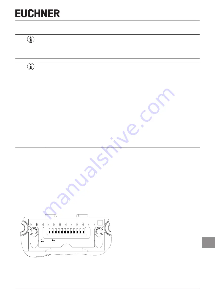
Set the FSoE address on the bus module MBM using the DIP switches.
A0 RST
OFF
ON
1
2
3
4
5
6
7
8
9
10 11 12
ON
CTS
Default: 000
00‘0000‘0000
WWW
A1
A2
A3
A4
A5
A6
A7
A8
A9
Important: Identical addresses must be set in the control system and on the device.
3.
Link safe bits.
4.
If necessary, set other parameters for the individual modules. You will find an overview of the possible parameters in
11.8.2. Setting parameters for modules and submodules on page 34


