


Operating Instructions
Non-Contact Safety Switch CES-AH-C03-AH-SM
26
(Translation of the original operating instructions) 106595-09-06/20
11.6.2. Operating distances
Actuating range for center offset m = 0
(only in combination with actuator CES-A-BRN)
Parameter
Value
Unit
min.
typ.
max.
Operating distance
-
27
-
mm
Assured operating distance s
ao 1)
20
-
-
Switching hysteresis
1)
-
3
-
Assured release distance s
ar
-
-
75
1) The values apply to surface installation of the actuator on steel.
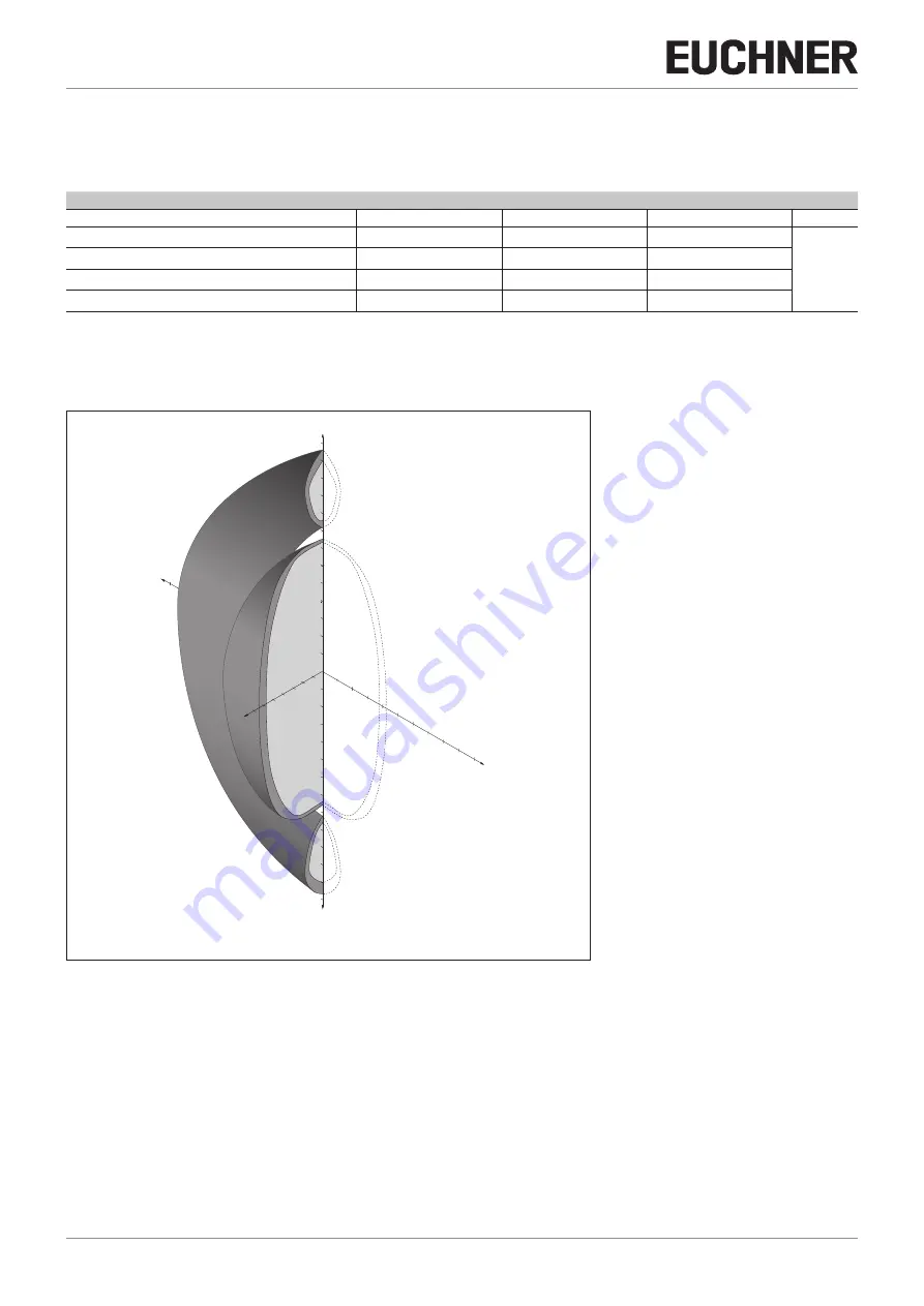
Typical actuating range
(only in combination with actuator CES-A-BRN on surface mounting on steel)
5
20
25
30
35
Z
X
5
15
20
50
45
40
35
30
25
50
Y
-5
-10
-15
-20
-25
-30
-35
-40
-45
-50
-55
-60
-65
10
5
15
25
30
40
45
50
55
60
65
15
10
10
20
35
For a side approach direction for the actuator and read head, a minimum distance of s = 6 mm must be maintained so that the
actuating range of the side lobes is not entered.
Figure 6:
Typical actuating range


