BEA--206006-EN-04
Page 7/16
Pneumohydraulic controller HP 036./HP 037.
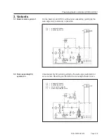
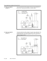
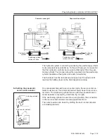
Web guiding is by the web edge (automatic) or servo center. The
positioning cylinder can be set via pushbuttons. A P/T connection is
possible with this valve assembly (please quote it however when or-
dering controller HP 03..).
HP 0360 20 bar
HP 0370 30 bar
- HZ
- FL
AIR
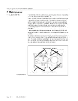
:S 2.1 :S 2.2
:S 1.1 :S 1.2
- SC
:S 1
:S 2
- Y 3
- Y 2
:A
:B
:A
:B
Y 10
Y 11
T
B
P
A
P
P
T
T
OIL
D 1
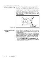
4. Mounting
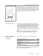
Controller HP 03.. should be mounted so that the air hoses and hy-
draulic lines to the sensor, return-to-center switch and positioning
cylinder are kept as short and straight as possible and are laid accor-
ding to the connection diagrams. The minimum bending radius is 50
mm (for air and hydraulic lines). Please ensure easy access to the
controller for operating and maintenance purposes.
Controller HP 03.. must be mounted a little higher than the positio-
ning cylinder to ensure the self-venting of the system.
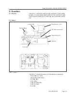
Do not drill the fluid tank
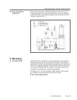
3.5 Valve assembly 06,
system 2ab
4.1 Controller HP 03..
FL
= air sensor
HZ
= positioning device
SC
= servo center actuato-
rY 2/Y 3 = solenoid valves
Y 10


