Pneumohydraulic controller HP 036./HP 037.
Page 12/16 BEA--206006-EN-04
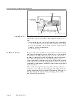
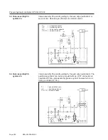
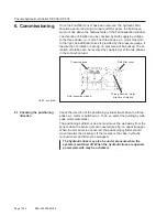
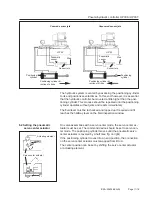
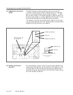
The basic setting when the pneumatic sensor is uncovered is
12 mbar (= 120 mm water column), measured at S 2. For sensitive
webs, the S 2 signal pressure can be reduced to approx. 9 mbar
(90 mm water column). The positioning speed is however also redu-
ced as the servo-valve is no longer actuated to its full extent. The air
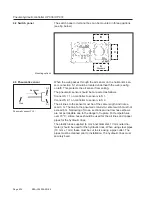
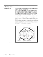
flow setting is effected via the AIR setscrew (see fig. below).
The setscrew is covered by a protective cap. Once the nut is loose-
ned, the signal pressure can be set. Subsequently, the nut should be
retightened and the protective cap replaced.
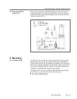
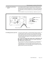
On commissioning, however, check for synchronous operation. The
positioning cylinder speed must be identical in both directions. If this
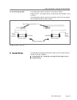
is not the case, turn the set screw for synchronous operation (see
illustration above) up approximately one full turn left or right until syn-
chronous operation is attained.
Minimum air pressure
Maximum air pressure
Setscrew
Setscrew for synchro-
nous operation
Setscrew
Protective cap
Nut
6.3 Adjusting the pneumatic
system
6.4 Setting synchronous
operation


