Pneumohydraulic controller HP 036./HP 037.
Page 10/16 BEA--206006-EN-04
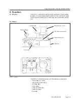
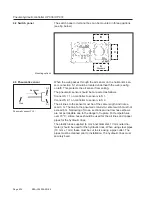
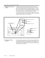
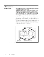
Once the fluid filler conver has been removed, the hydraulic fluid
should be poured in using a funnel and filter paper. the fluid leven
must not rise above the halfway mark on the fluid inspection window.
The direction of rotation can be checked by briefly applying voltage
to the three phase a.c. motor. The three phase a.c. motor must turn
to the right. An additional check is provided by the pressure gauge, if
the direction of rotation is wrong, no pressure will be built up. The di-
rection of rotation can be revers ed by swapping over the two phases
in the connection lead.
6. Commissioning
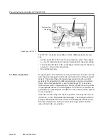
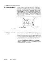
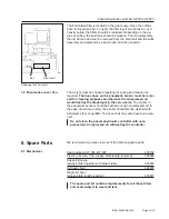
Check the direction of the positioning cylinder travel when the three-
phase a.c. motor is switched on. To do so, select the gui ding by web
edge mode (automatic).
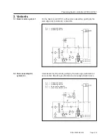
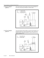
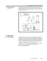
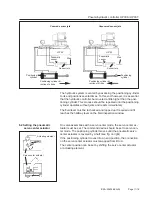
The positioning cylinder or device must move the web away from the
sensor when the sensor jets are covered (see fig. on opposite page).
When the air sensor is uncovered, the positioning cylinder should
move towards the air sensor. If the reverse is the case, hydraulic
connections A and B must be swapped.
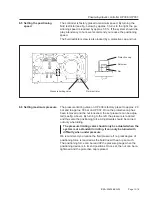
The hydraulic lines may also be under pressure when the
system is switched off. When the hydraulic lines are opened,
power elements may be activated.
Fluid filler cover
Three-phase a.c. motor
direction of rotation
Fluid inspection window
Pressure gauge
HP 03.. controller
6.1 Checking the positioning
direction


