7
5. Connection to the digital system
We recommend that you first configure the SignalPilot decoder
completely and only then install it in the layout.
5.1. Terminals
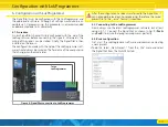
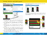
Fig. 1 shows the SignalPilot with all terminals.
a) Daylight signals, motorised turnout-drives or similar loads shall
be connected to the terminals labelled 1 to 16 for outputs 1
to 16. Each output can be set by software as a „pull” level
(against U+) or „pull” level (against ground).
b) The
terminals PW A
and
PW B
serve as the power supply
connecting pints of the SignalPilot. You can either use the digi-
tal track voltage or use an external power supply. An external
power supply is particularly recommended for larger layouts,
because the electric energy does not have to be taken from the
command station or booster.
c) Connect the T
erminals Trk A
and
Trk B
to the track output of
the command station (or boosters) from which the SignalPilot
should receive its commands.
d) Terminals
U+
. The return wire of the connected accessories
(lamps. LEDs, solenoids, etc.) can be connected to these ter-
minals. The voltage is equal to the supply voltage (i.e.: track
voltage).
e) Terminals
GND
. Alternatively the return wires of the connected
loads can be connected to these terminals, provided that the
output has been configured as a „pull” output stage.
f) The „PROG” LED serves together with the
g) Programming button for setting the POM address of the Sig-
nalPilot. This process is described in chapter 9.
h) Power LED. Is turned on as soon as the SignalPilot receives po-
wer.
i) Extension socket for the SwitchPilot Extension relay module.
Figure 1: Connections of the SignalPilot
Connection to the digital system
g)
i)
f)
c)
b)
a)
d)
e)
a)
j)


