10
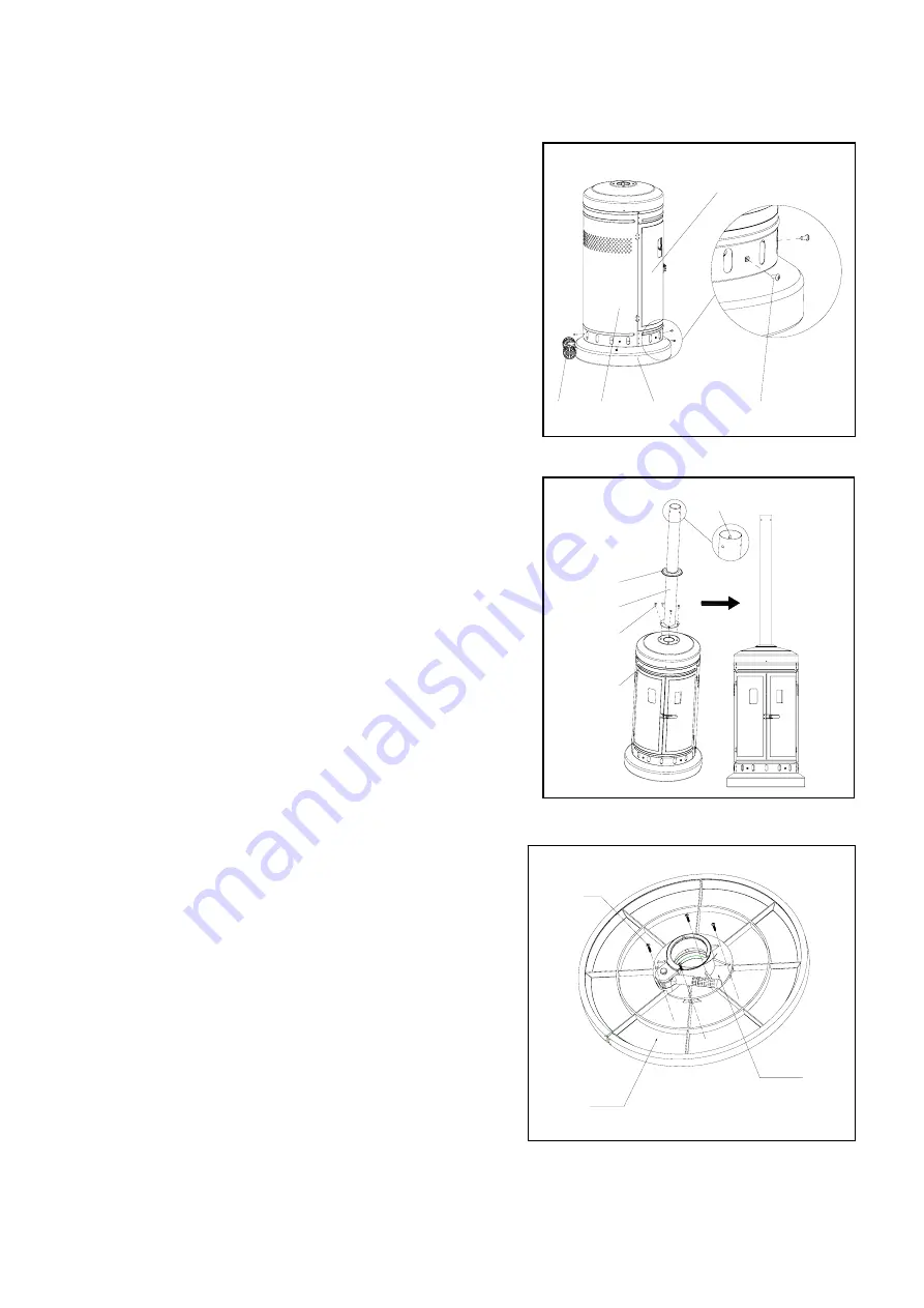
Fig.2
2, Turn the base (J) right-side up, then attach cylinder
assembly (H) using M5 x 8 mm black bolts (BB)
though preassembled L-pins.
Note: The door on the cylinder assembly (H)
should be on the opposite side of the wheel
assembly (I).
Fig.3
Fig.4
3,
Attach pole assembly (G) to cylinder assembly (H)
using M6 x 10 mm bolts (EE).
Note: Ensure the pole assembly (G) is straight.
Then, use deck ring (F) to cover connection.
4, Attach table support assembly (E) to table
assembly (D) with M4 x 12 mm Bolt (KK).
Door
I
H
BB
J
Back
F
G
H
EE
KK
E
D
Summary of Contents for 640-08477458-7
Page 19: ......


