Tilt the Flow Control Valve Rocker, Figure 13, rearward
for the maximum rate of correction and forward for the
minimum correction rate. The rate of oil flow (correction)
of the hydraulic system is infinitely variable between
these two points.
Pull the Draft Control Lever to the top of the quadrant to
override the Flow Control Valve and raise the implement
quickly.
NOTE: When operating in Draft Control, the Position
Control Lever, Figure 11, should normally be at the
bottom of the quadrant. However, the Position Control
Lever may be used in conjunction with Draft Control to
limit the maximum depth of correction to achieve a more
even depth of cultivation in fields with widely varying
soil conditions.
When grading and backfilling with light equipment, such
as a rear blade, it may be desirable to prevent the blade
from “diving”. This is accomplished by using the Position
Control Lever in conjunction with the Draft Control Lever.
See “Draft Control Operation with Position Control” on
this page.
Position Control Operation
Set the required implement height/depth using the
Position Control Lever, Figure 11. Pull the Lever Back
to raise the implement height/depth using the Position
Control Lever. Pull the lever back to raise the implement,
push forward to lower. Implement height/depth is relative
to the position of the Lever in the quadrant.
When the required implement working height/depth has
been established, set the adjustable stop adjacent to
the Position Control Lever to locate the position for
repeated use. The Lever may be eased sideways when
it is required to by pass the adjustable stop.
The adjustable stop is reversible after loosening the
central clamp screw so that it may also be used when
operating in Draft Control.
When operating in Position Control it is of no advantage
to restrict the oil flow in the hydraulic system. However,
the manual flow control valve (where fitted) may be used
to reduce the rate of lift of the three-point linkage, if
required. To reduce the rate of lift, tilt the Flow Control
Valve Rocker, Figure 13, forward. Tilt the Rocker rearward
to increase the rate of lift.
IMPORTANT : When transporting equipment on the
three-point linkage set the adjustable stop to maintain
the Position Control Lever in the raised position. This
will prevent accidental movement of the lever which
could result in attached equipment lowering and
becoming damaged or damaging the road surface.
Draft Control operation with Position Control
Position Control may be used together with the Draft
Control as follows:
Set the Position Control Lever at the maximum desired
implement depth. The hydraulic system will not lower
the implement below this depth. This will also prevent
“diving” which may be encountered will light equipment,
such as a rear blade, when grading or backfilling.
Adjust the Draft Control Lever for the maximum required
draft load (pull).
The hydraulic lift system will now provide normal draft
response within the range set by the Position Control.
This adjustment provides a more uniform depth while
maintaining an even pull in widely varying soil
conditions.
AUXILIARY SERVICES
Accessory Cover (Where fitted)
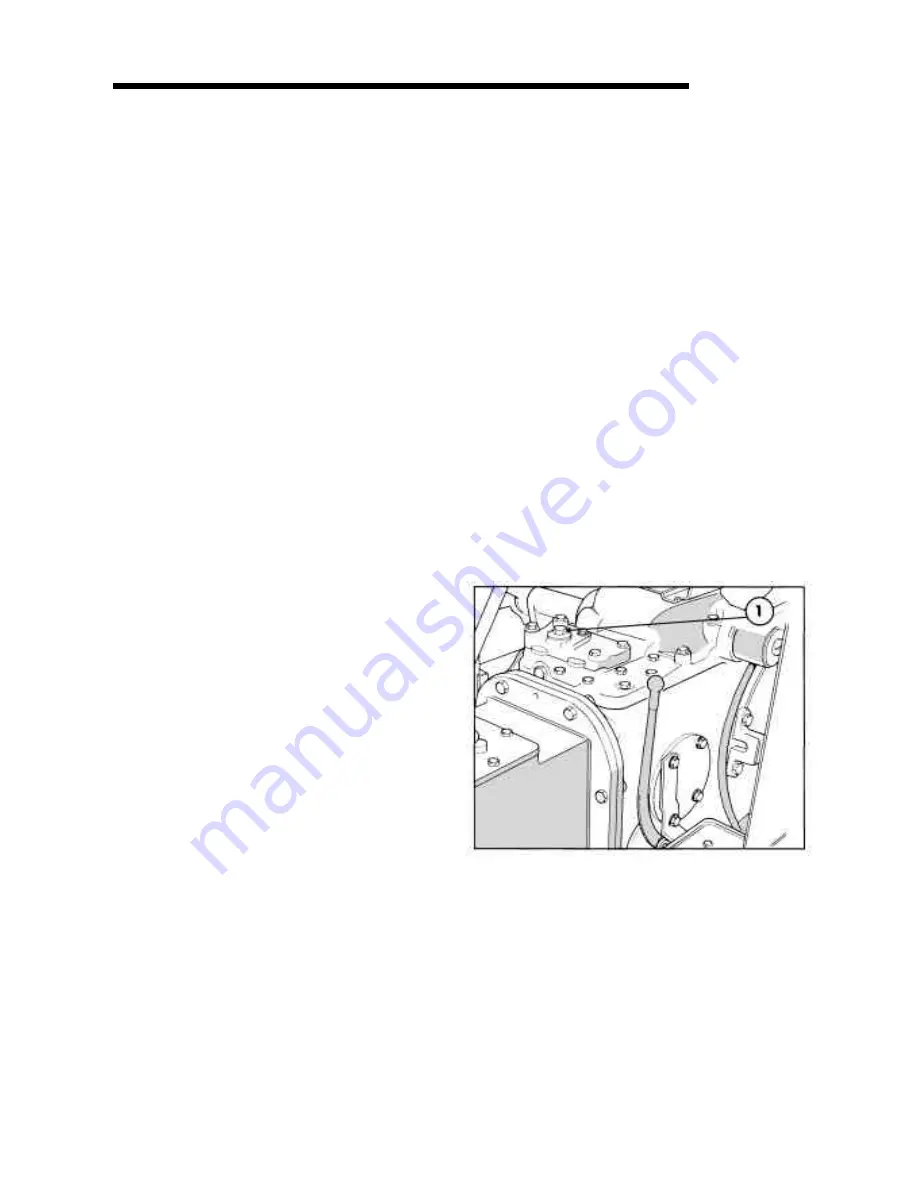
The live tapping on top of the accessory cover (where
fitted), Figure 14, is connected directly into the tractor
hydraulic circuit. A remote cylinder connected to the
live tapping may be extended or retracted, in conjunction
with the three-point linkage, by moving the Draft Control
Lever.
SECTION A
11
Operating Remote Cylinders with the A.S.C.
Valve (where fitted)
The optional Auxiliary Services Control (A.S.C.) Valve
is installed in place of the accessory cover or remote
control valves and may be supplied with pipe work
leading to a convenient coupling at the rear of the tractor.
Alternatively, remote cylinders may be connected
directly into the tapping on top of the A.S.C. valve. See
Figure 15.
14. Accessory Cover
1. Live tapping


