background image

-- 46 --

bu12d04a

7.3

Recall

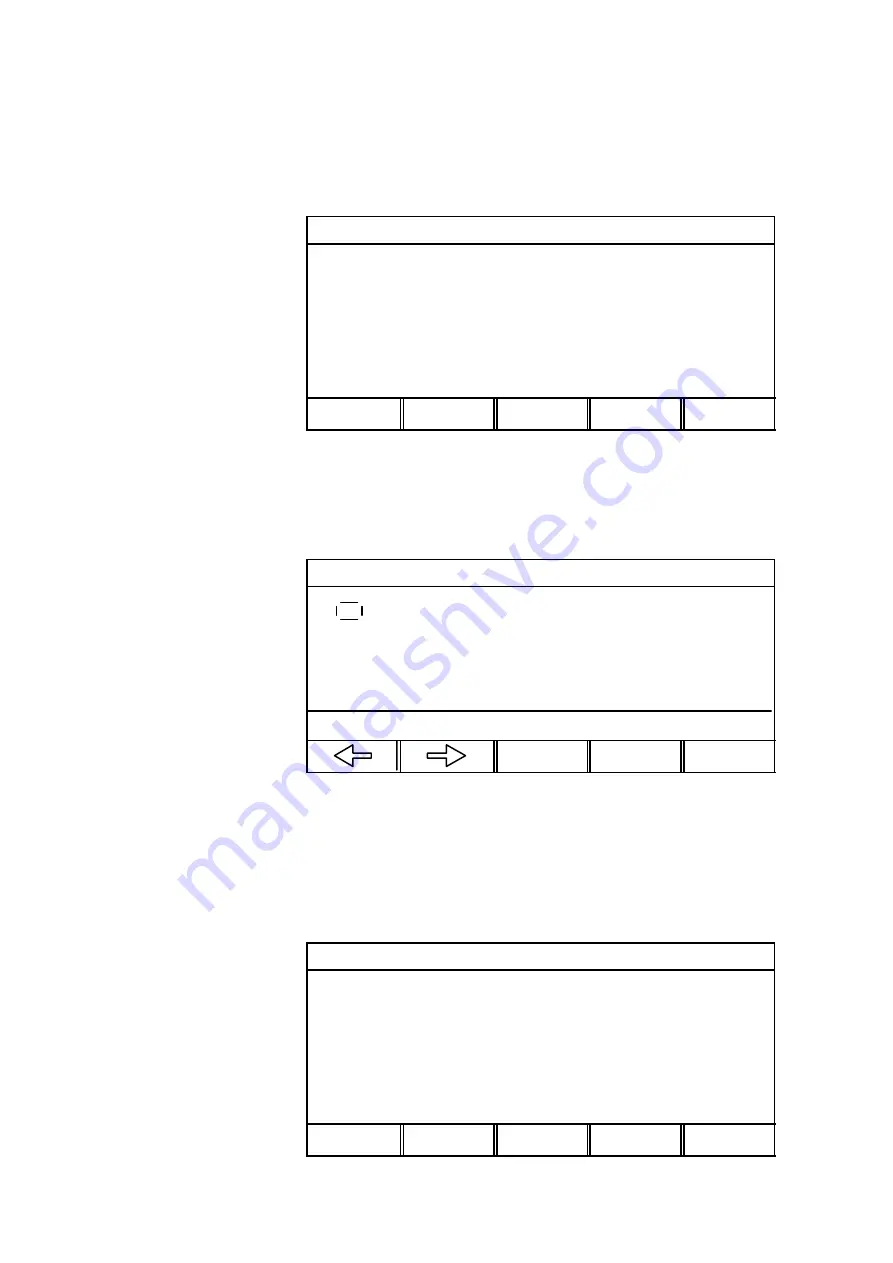
If you want to call in a stored data set--up; make sure you are in the memory

menu.Press the RECALL button.

MEMORY FUNCTIONS -- STORED WELD PARAM.

10

STORE

DELETE

RECALL

COPY

QUIT

Example

The most recently stored data set--up is automatically marked. If there is more than

one stored data set--up, you can move the cursor between these with the left and

right arrow button.

RECALL MEMORY NR. 10

Press ENTER to

confirm that you

want to recall data

set number 10.

10

"

DIP/SPRAY. Metal cored Fe. Ar+8% CO2

QUIT

ENTER

Use the QUIT button to return to the memory menu.

7.4

Copy

You can copy the contents in a weld data set--up to a new memory location. Start by

pressing the COPY button.

MEMORY FUNCTIONS -- STORED WELD PARAM.

10

STORE

DELETE

RECALL

COPY

QUIT

Summary of Contents for PUA 1

Page 1: ...Valid for program version 3 04V 0456 685 128 010815 PUA 1 ...

Page 2: ... 2 Rights reserved to alter specifications without notice Sous réserve de modifications sans avis préalable ENGLISH 3 FRANÇAIS 81 ...

Page 3: ...gic Mode 26 3 2 Basic Settings 26 3 3 Weld data 27 3 4 STICK configuration 28 3 5 Setting Example STICK 28 4 TIGWelding 30 4 1 Basic Settings 30 4 2 Weld Data Settings 31 4 3 TIG configuration 33 4 4 Setting Example TIG 33 5 CARBON ARC GOUGING 38 5 1 Synergic Mode 38 5 2 Basic Settings 38 5 3 Weld Data 38 5 4 Setting Examples for Carbon Arc Gouging 39 6 MEASUREMENT TEST PICTURE 41 6 1 Description ...

Page 4: ...9 2 Configuration 52 9 3 Quality Functions 66 9 4 Production Statistics 67 9 5 Error Log 68 9 6 User Defined Synergic Lines for MIG 71 9 7 Serial Communication 74 9 8 Upgrading the Software 75 10 APPENDIX 78 10 1 Setting Ranges and Setting Steps 78 10 2 Menu structure 80 ...

Page 5: ...nal page of this publication for a figure illustrating the menu structure 1 1 Main menu ESAB LUD 450 PROCESS MIG METHOD DIP SPRAY WIRE TYPE Metal cored Fe SHIELDING GAS Ar 2O CO2 WIRE DIAMETER 0 040 1 0mm AUXILIARY FUNCTIONS SET MEASURE MEMORY FAST MODE ENTER 1 2 Using the Controller The controller can be said to consist of two units the working memory and the weld data memory WELD DATA MEMORY WOR...

Page 6: ...sh French Czech Portuguese How to Choose the Language and Unit of length Start by pressing the MENU button to open the main menu ESAB LUD 450 Position the cursor using the arrow button on the row for AUXILIARY FUNCTIONS press ENTER PROCESS MIG METHOD DIP SPRAY WIRE TYPE Metal cored Fe SHIELDING GAS Ar 8 CO2 WIRE DIAMETER 0 040 1 0mm AUXILIARY FUNCTIONS SET MEASURE MEMORY FAST MODE ENTER AUXILIARY ...

Page 7: ...EFAULTS MULTIPLE WIRE FEEDERS UNIT OF LENGTH Inch QUIT ENTER Position the cursor on the line for language choice and press ENTER AUXILIARY FUNCTIONS CONFIGURATION Press ENTER to call up a list of options LANGUAGE US ENGLISH LOCK FUNCTION OFF REMOTE CONTROLS MIG DEFAULTS STICK DEFAULTS TIG DEFAULTS GENERAL DEFAULTS MULTIPLE WIRE FEEDERS UNIT OF LENGTH Inch QUIT ENTER Position the cursor on the line...

Page 8: ...is shown in this manual as a box around the selected text The controller cursor actually appears as a shaded field with the selected text highlighted in white Text Boxes At the bottom of the display are five boxes containing text that explains the current functions of the five keys in a line below them Save Mode To extend the life of the display illumination it is switched off after three minutes ...

Page 9: ...ecreases a setting in small steps If the button is held down longer the size of the steps increases Soft buttons The five buttons called soft buttons are along the bottom edge of the display window These can have varying functions depending on your location in the menu structure Texts indicating the current button functions are shown at the bottom of the display a white dot beside a function text ...

Page 10: ...arrow at the top or bottom of the list indicates that more options will become visible if you scroll up or down using the arrow buttons 1 6 3 ON OFF or YES NO Settings With certain functions you can switch the setting to ON or OFF or to YES or NO The synergetic function in MIG and STICK welding is an example of such a function ON OFF or YES NO settings can be selected in either of two ways You can...

Page 11: ...nt may be used with MIG welding The user sets the values for S method S wire type S shielding gas S wire dimension Based on these basic settings and the value specified for wire feed speed a microprocessor works out suitable values for the various welding technical parameters These parameter types are dependent on the chosen welding method dip spray or pulse For more information see Weld data sett...

Page 12: ... O2 0 8 1 0 1 2 1 6 Ar 32 He 3 CO2 1 H2 0 8 0 9 1 0 1 2 1 6 Stainless duplex wire Ss duplex Ar 2 O2 1 0 Ar 30 He 1 O2 1 0 Mg alloyed aluminum wire AlMg Ar 0 9 1 0 1 2 1 6 Siliconized aluminum wire AlSi Ar 0 9 1 0 1 2 1 6 Ar 50 He 0 9 1 0 1 2 1 6 Metal cored wire Fe Ar 20 CO2 1 0 1 2 1 4 1 6 Ar 8 CO2 1 0 1 2 1 4 1 6 Rutile flux cored wire Fe CO2 1 2 1 4 1 6 Ar 20 CO2 1 2 1 4 1 6 Basic flux cored wi...

Page 13: ... 0 1 2 1 6 Ar 2 CO2 0 8 0 9 1 0 1 2 1 6 Ar 30 He 1 O2 0 8 1 0 1 2 1 6 Ar 3 CO2 1 H2 0 8 1 0 1 2 1 6 Ar 32 He 3 CO2 1 H2 0 8 0 9 1 0 1 2 1 6 Stainless duplex wire SS Duplex Ar 30 He 1 O2 1 0 Ar 2 O2 1 0 Magnesium alloyed aluminum wire AlMg Ar 0 8 0 9 1 0 1 2 1 6 Siliconized aluminum wire AlSi Ar 1 0 1 2 1 6 Ar 50 He 1 0 1 2 1 6 Metal cored wire Fe Ar 20 CO2 0 9 1 0 1 2 1 4 1 6 Ar 8 CO2 0 9 1 0 1 2 ...

Page 14: ... current S Ka S Ki A table of parameter setting ranges is given in the APPENDIX under section 10 2 5 Start and stop data The following settings affect the start and stop cycles for MIG welding Under the respective headings are all settings that affect the start cycle and welding stop Start settings Stop settings S Gas pre flow S Gas post flow S Creep start S Hot start S Hot start time S Increase w...

Page 15: ...s continues to flow before and after welding Burnback Time Burnback time is used to adjust the length of the electrode after welding 2 6 Gas Purge Cold Wire Feed and 2 Stroke 4 Stroke The following three functions can be controlled with soft button as can functions such as hot start For a description of how this is done see MIG configuration under section 9 2 4 2 Gas purge The gas purge function i...

Page 16: ...ashed line The crater fill can also be interrupted when the torch trigger is quickly pressed in and then released during the crater fill 4 Stroke Crater fill Gas post flow Gas pre flow 1 2 3 4 Craterfill final data Welding Hot Start During 4 stroke gas pre flow starts when the torch trigger is pressed in 1 When the torch trigger is released 2 welding data goes up to the pre set values When the tor...

Page 17: ...MENU key to bring up the main menu We will make the following five settings S PROCESS MIG S METHOD DIP SPRAY S WIRE TYPE Fe S SHIELDING GAS Ar 8 CO2 S WIRE DIAMETER 0 040 1 0mm Process ESAB LUD 450 The first setting is the type of welding process Use the arrow buttons to select the line for PROCESS Press ENTER to call up a list of options PROCESS MIG METHOD PULSE WIRE TYPE Metal cored Fe SHIELDING...

Page 18: ...d press ENTER We have now set METHOD DIP SPRAY Wire Type ESAB LUD 450 Position the cursor on the line for WIRE TYPE Press ENTER to to call up a list of options PROCESS MIG METHOD DIP SPRAY WIRE TYPE Metal cored Fe SHIELDING GAS Ar 8 CO2 WIRE DIAMETER 0 040 1 0mm AUXILIARY FUNCTIONS SET MEASURE MEMORY FAST MODE ENTER Here is an example of a list with so many options that they cannot all be displaye...

Page 19: ...0 1 0mm AUXILIARY FUNCTIONS SET MEASURE MEMORY FAST MODE ENTER Position the cursor on the line for Ar 8 CO2 and press ENTER We have now set SHIELDING GAS Ar 8 CO2 Wire Diameter ESAB LUD 450 Position the cursor on the line for WIRE DIAMETER Press ENTER to call up a list of options PROCESS MIG METHOD DIP SPRAY WIRE TYPE Metal cored Fe SHIELDING GAS Ar 8 CO2 WIRE DIAMETER 0 040 1 0mm AUXILIARY FUNCTI...

Page 20: ...he synergic function many of these settings will be handled by a microprocessor We begin by pressing the MENU button to display the main menu Press the SET button to view the settings menu We ll now make the following settings S WIRE FEED SPEED 393 in min 10 0 m min Wire Feed Speed WELD PARAMETERS Position the cursor on the line WIRE SPEED Set it to 393 in min 10 0 m min using VOLTAGE 29 0 0 0 V W...

Page 21: ...T button to view the settings menu WELD PARAMETERS Position the cursor on the line START DATA and press ENTER VOLTAGE 29 0 0 0 V WIRE SPEED 393 in min 10 0 m min INDUCTANCE 80 SYNERGIC MODE ON START DATA STOP DATA CRATR FILL HOT START 4 STROKE QUIT ENTER Gas Pre Flow Time Here you enter the length of time you want the shielding gas to flow before welding begins START DATA SYNERGIC MODE Position th...

Page 22: ... use the hot start function If you decide to use the hot start function you should then enter the hot start time and any increase in the wire feed speed START DATA SYNERGIC MODE Position the cursor on the line HOT START Press enter to call up a list of options Set it to YES GASPREFLOW 0 8 s CREEPSTART YES HOT START YES HOT START TIME 1 0s WIRE SPEED 51 in min CRATER FILL HOT D START 4 STROKE QUIT ...

Page 23: ... 1 0 s WIRE SPEED 98 in min 2 5 m min CRATR FILL HOT D START 4 STROKE QUIT 2 8 4 Stop Data Settings The stop data menu is used to make the settings that affect the stop sequence during MIG welding We will enter the following stop data S CRATER FILL YES S CRATER FILL TIME 1 5 s S FINAL WIRE FEED SPEED 118 in min 3 0 m min S BURNBACK TIME 0 11 s S GAS POST FLOW 2 0 s Make sure that the settings menu...

Page 24: ...QUIT Crater Fill Time STOP DATA SYNERGIC MODE Position the cursor on the line TIME Set it to 1 5 s using one of the plus minus buttons CRATERFILL YES TIME 1 5 s FINAL WIRE SPEED 393 in min BURNBACKTIME 0 12 s GASPOSTFLOW 0 5 s CRATR D FILL HOT D START 4 STROKE QUIT Final Wire Feed Speed This is used to set the wire feed speed that will be used when crater fill is complete STOP DATA SYNERGIC MODE P...

Page 25: ...KE QUIT Gas Post Flow Use this to set the time for which the gas continues to flow after welding is complete STOP DATA SYNERGIC MODE Position the cursor on the line GAS POST FLOW Set it to 2 0 s using one of the plus minus buttons CRATERFILL YES TIME 1 5 s FINAL WIRE SPEED 118 in min 3 0 m min BURNBACKTIME 0 11 s GASPOSTFLOW 2 0 s CRATR D FILL HOT D START 4 STROKE QUIT This completes the stop data...

Page 26: ...ing are entered using the controller s main menu 1 Welding Process STICK 2 Electrode Type Three different types of electrodes can be chosen for welding in synergetic mode S Basic S Rutile S Cellulosic 3 Electrode Diameter The table below shows the electrode diameters that can be selected when the power source is in synergic mode Electrode type Electrode diameter Basic 1 16 1 6 3 32 2 1 8 2 5 5 32 ...

Page 27: ...tomatically whenever the welding current is adjusted In the settings menu you can see what value has been chosen for the parameter welding current ESAB LUD 450 Display the SETUP menu by pressing the SET button PROCESS STICK ELECTRODE TYPE BASIC E7018 ELECTRODE DIAMETER 1 8 2 5mm AUXILIARY FUNCTIONS SET MEASURE MEMORY FAST MODE ENTER WELD PARAMETERS With our chosen combination of electrode type and...

Page 28: ...o select PROCESS Press ENTER to call up a list of options PROCESS STICK ELECTRODE TYPE BASIC E7018 ELECTRODE DIAMETER 1 4 6mm AUXILIARY FUNCTIONS SET MEASURE MEMORY FAST MODE ENTER Position the cursor over the STICK option in the list and press ENTER We have now set PROCESS STICK Electrode Type ESAB LUD 450 Use the arrow buttons to select ELECTRODE TYPE Press ENTER to call up a list of options PRO...

Page 29: ...m AUXILIARY FUNCTIONS SET MEASURE MEMORY FAST MODE ENTER Position the cursor on the line for 1 8 2 5mm in the list and press ENTER We have now set ELECTRODE DIAMETER 1 8 2 5mm ESAB LUD 450 PROCESS STICK ELECTRODE TYPE RUTILE ELECTRODE DIAMETER 1 8 2 5mm AUXILIARY FUNCTIONS SET MEASURE MEMORY FAST MODE ENTER The next line in the main menu is AUXILIARY FUNCTIONS See the section on AUXILIARY FUNCTION...

Page 30: ...if the TIG torch trigger will have a 2 stroke or 4 stroke function The primary difference is that with 2 stroke the trigger is held down during welding while with 4 stroke the trigger can be released The difference between 2 stroke and 4 stroke is illustrated in the following figures along with other functions of the start and stop cycles 2 Stroke Gas pre flow Slope up Slope down Gas post flow 1 2...

Page 31: ...er is released again 4 the arc is extinguished and any gas post flow starts Use one of the soft keys in the settings menu to switch between 2 stroke and 4 stroke 4 2 Weld Data Settings The weld parameter values are set in the settings menu Certain parameters are specified for the selected method and certain are common for both the TIG methods The following parameters are set for TIG welding A tabl...

Page 32: ...KGROUND CURRENT PULSE TIME BACKGROUND TIME Current Time Pulse Time and Background Time Pulse time specifies the time for current pulses Background time specifies the time for background current For welding with pulsed current see the figure above The settings range for both pulse time and background time is 0 001 5 000 s Gas Pre flow and Gas Post flow The parameters for gas pre flow and gas post f...

Page 33: ...one by pressing the MENU button We will make the following four settings S PROCESS TIG S METHOD CONSTANT DC S START METHOD TOUCH TIG S TRIGGER MODE 2 STROKE Process ESAB LUD 450 Use the arrow buttons to select PROCESS Press ENTER to call up a list of options PROCESS STICK ELECTRODE TYPE BASIC E7018 ELECTRODE DIAMETER 1 8 2 5mm AUXILIARY FUNCTIONS SET MEASURE MEMORY FAST MODE ENTER Position the cur...

Page 34: ...DE ENTER Position the cursor on the line for CONSTANT DC in the list and press ENTER We have now set METHOD CONSTANT DC Start Method ESAB LUD 450 Position the cursor on the line START METHOD Press ENTER to call up a list of options PROCESS TIG METHOD CONSTANT DC START METHOD TOUCH TIG GUN TRIGGER MODE 4 STROKE AUXILIARY FUNCTIONS SET MEASURE MEMORY FAST MODE ENTER Position the cursor on the line f...

Page 35: ...ARY FUNCTIONS SET MEASURE MEMORY FAST MODE ENTER Position the cursor on the line for 2 STROKE in the list and press ENTER We have now set TRIGGER MODE 2 STROKE ESAB LUD 450 PROCESS TIG METHOD CONSTANT DC START METHOD TOUCH TIG GUN TRIGGER MODE 2 STROKE AUXILIARY FUNCTIONS SET MEASURE MEMORY FAST MODE ENTER The next line in the main menu is AUXILIARY FUNCTIONS See the section AUXILIARY FUNCTIONS un...

Page 36: ...buttons to set the value to 200 A CURRENT 200 A SLOPE UP TIME 4 0 s SLOPE DOWN TIME 6 0 s GASPREFLOW 2 5 s GASPOSTFLOW 3 3 s GAS PURGE 4 STROKE QUIT Slope up and Slope down The slope up and slope down parameters are each connected to a plus minus button The upper key is used for setting of slope up and the lower button is used for setting of slope down WELD DATA SETTING Place the cursor on the row...

Page 37: ...plies during setting of gas pre flow and the lower button is used during setting of gas post flow WELD DATA SETTING Place the cursor on the row for GAS PRE FLOW and GAS POST FLOW Set GAS PRE FLOW to 3 s by stepping with the upper plus minus button CURRENT 200 A SLOPE UP TIME 2 0 s SLOPE DOWN TIME 1 4 s GASPREFLOW 3 0 s GASPOSTFLOW 3 3 s GAS PURGE 4 STROKE QUIT WELD DATA SETTING Set GAS POST FLOW t...

Page 38: ...on arc gouging are made in the controller s main menu 1 Weld Process CARBON ARC GOUGING 2 Electrode Diameter The following table shows the electrode diameters which can be selected in accordance with the weld current source s synergy Electrode Diameter 3 16 in 4 mm 5 mm 1 4 in 6 mm 8 mm 5 3 Weld Data If only weld current source synergy is used it is not necessary to set any weld data The parameter...

Page 39: ... mm AUXILIARY FUNCTIONS SET MEASURE MEMORY FAST MODE ENTER Position the cursor on the line marked CARBON ArcAir in the list and press ENTER We have now set PROCESS CARBON ARC GOUGING Electrode Diameter ESAB LUD 450 Use the arrow buttons to select the line ELECTRODE DIAMETER Press ENTER to call up a list of options PROCESS CARBON ArcAir ELECTRODE DIAMETER 6 mm AUXILIARY FUNCTIONS SET MEASURE MEMORY...

Page 40: ...adjust the voltage setting ESAB LUD 450 Go to the settings menu by pressing the SET button PROCESS CARBON ArcAir ELECTRODE DIAMETER 1 4 in 6 mm AUXILIARY FUNCTIONS SET MEASURE MEMORY FAST MODE ENTER WELD DATA SETTING On the basis of our electrode diameter setting the power source has set the voltage to 41 V VOLTAGE 41 0 V SYNERGIC MODE ON QUIT ...

Page 41: ...made under the MIG basic settings See section 9 2 4 3 If you want to call up the measurement test picture make sure that the main menu appears in the character display Press the MEASURE button ESAB LUD 450 PROCESS MIG METHOD DIP SPRAY WIRE TYPE Metal cored Fe SHIELDING GAS Ar 8 CO2 WIRE DIMENSION 0 040 1 0mm AUXILIARY FUNCTIONS SET MEASURE MEMORY FAST MODE ENTER This is how the measurement display...

Page 42: ...s can be changed in the measurement test picture Which parameters these are depends on which weld process has been set The parameter values which can be adjusted are always marked with or DIP SPRAY Metal cored Fe Ar 8 CO2 Change by pressing or The window that pops up will disappear after 1 5 s if neither of the buttons are used 22 5 Volt 134 Amp 152 in min VOLTAGE 22 5 3 5 V REM QUIT ...

Page 43: ...you want to store a set of data first make sure that the main menu is displayed Press the MEMORY button If the weld data memory is empty the display will appear as follows MEMORY FUNCTIONS STORED WELD PARAM NO STORED DATA SETS STORE QUIT Example We will now store a set of weld data We will store it in memory location 10 Press the STORE button The display will appear as follows STORE MEMORY NO 1 If...

Page 44: ...Press ENTER QUIT ENTER The data set up is now stored as number 10 It is possible to view parts of the content in data set up number 10 farthest down in the character display STORE IN DATA NR 10 10 DIP SPRAY Metal cored Fe Ar 8 CO2 QUIT ENTER To return to the memory menu press the QUIT button Tip If the display indicates STORE IN DATA NR 1 you can go directly to set 99 by pressing the minus on eith...

Page 45: ...EMORY NO 10 10 DIP SPRAY Metal cored Fe Ar 8 CO2 STORE DELETE RECALL COPY QUIT The most recently stored data set up is automatically marked If there is more than one stored data set up the cursor can be moved between these with the left and right arrow button DELETE MEMORY NR 10 Press ENTER to confirm you want to delete data set number 10 10 DIP SPRAY Metal cored Fe Ar 8 CO2 QUIT ENTER ...

Page 46: ...is more than one stored data set up you can move the cursor between these with the left and right arrow button RECALL MEMORY NR 10 Press ENTER to confirm that you want to recall data set number 10 10 DIP SPRAY Metal cored Fe Ar 8 CO2 QUIT ENTER Use the QUIT button to return to the memory menu 7 4 Copy You can copy the contents in a weld data set up to a new memory location Start by pressing the CO...

Page 47: ...cation to which you want to copy COPY MEMORY NO 10 TO NO 50 Go to number 50 with the plus button and press ENTER 10 DIP SPRAY Metal cored Fe CO2 0 045 QUIT ENTER STORE OVER EXISTING WELD DATA 10 DIP SPRAY Metal cored Fe CO2 0 045 NO YES Weld data number 10 has now been copied to memory location 50 If memory location 50 was already occupied this information would appear in the character display COP...

Page 48: ...lso adjust the voltage based on the weld program you have chosen to recall Analogue remote control With analogue remote control you can regulate the primary parameters for the welding process from a device other than the controller S Aristo Control Synergic PAE 2 With this type of remote control you can increase or decrease the wire feed speed and voltage based on the selected synergetic line S ES...

Page 49: ...e the picture can appear like this DIP SPRAY Metal cored Fe Ar 8 CO2 22 5 Volt 134 Amp 152 in min WELD DATA 1 WELD DATA 2 WELD DATA 3 WELD DATA 4 2ND FUNCT Four of the soft buttons can thus be linked to a weld data setting of their own in the weld data memory See soft button function under section 9 2 4 2 The fifth soft button s 2nd function is used to shift functions for the four soft buttons You...

Page 50: ...lowing display is shown MEMORY CARD FUNCTION WELD DATA SETTINGS STORE DELETE RECALL QUIT STORE Used to store valid weld data settings occupied memory locations 1 99 from the controller to the PC card If the same weld data is already stored on the card it is written over by that which exists in the controller s own memory Exempel The weld data settings in the controller are The PC card is empty PC ...

Page 51: ...Setting control 1 2 3 10 12 50 2 3 4 5 6 Setting control 1 2 3 4 5 6 10 12 50 The controller now has 3 new sets of weld data settings 4 5 6 and sets 2 and 3 have been updated with the settings that were stored on the PC card Error codes If the controller indicates a fault in the PC card an error message appears which briefly describes the error in question Check the following S That the PC card is...

Page 52: ...is to enter the correct password LOCK FUNCTION LOCK STATUS OFF SET CHANGE LOCK CODE QUIT ENTER In PASSWORD MODE the lock function can be activated or deactivated without erasing the existing password should the function be deactivated If no password is stored and you try to activate the lock function a computer like keyboard view is displayed for entering a new code A small icon with a key is disp...

Page 53: ...firmed with the Enter button on the keyboard If the code is incorrect a warning message is shown giving the user the choice of either trying again or returning to the original view e g the measurement view or quick settings view If the code is correct all menu restrictions are lifted but the lock function remains activated This means that the user can leave the measurement and quick settings views...

Page 54: ...nabled the original data from the memory position currently in use is recalled after each welding stop In other words if you make a change relating to the synergic line for example increasing the voltage by 2 V weld and stop the voltage change is discarded and the original data recalled This can be useful when testing new welding data for example Configuration for digital remote control When using...

Page 55: ...1 VOLTAGE ANALOG 2 NONE RANGE ON INPUTS ANALOG 1 DIG MIN 8 0 V MAX 60 V QUIT ENTER If you position the cursor on the line ANALOG 2 and press ENTER a list appears It is now possible to choose if the potentiometer ANALOG 2 will be used WIRE FEED SPEED or if it will not be used NONE Select the line WIRE FEED SPEED and press ENTER CONFIGURATION REMOTE CONTROL The following character display appears DI...

Page 56: ... to select the line GUN TRIGGER MODE Press ENTER to to call up a list of options GUN TRIGGER MODE 4 STROKE SOFT KEYS SETUP VOLT MEASURE IN PULSED AVERAGE QUIT ENTER Position the cursor on the line for 2 STROKE in the list and press ENTER We have now set TRIGGER MODE 2 STROKE CONFIGURATION MIG DEFAULTS GUN TRIGGER MODE 2 STROKE SOFT KEYS SETUP VOLT MEASURE IN PULSED AVERAGE QUIT ENTER ...

Page 57: ... S Trigger weld data switch ON OFF To assign one of these functions to a soft button see the following instructions The following screen appears in the character display There are two columns in this picture one for function and one for button number The numbers 1 2 and 3 each represent their own button i e the button farthest to the left is number 1 etc We will assign button number 1 the function...

Page 58: ...gether with a button number in the right column To assign a new function to a button place the cursor on the row NONE and press the soft button you want to change In the display you ll see the button text NONE and you can now assign the button a new function 9 2 4 3 Average pulsed voltage MAIN MENU AUXILIARY FUNCTIONS CONFIGURATION MIG DEFAULTS VOLT MEASURE IN PULS Alternatives for voltage methods...

Page 59: ...he electrical push wire feed unit dispatches the wire A motor power value of 1 50 A is preset providing torque suitable for most wires and various hose bundle lengths If a soft thin aluminum wire is used it can sometimes be appropriate to reduce the motor power to 1 25 A to avoid problems with wire tangling If you have a worn wire liner for example a 16 m hose bundle and wire feed is beginning to ...

Page 60: ...top as possible without burning the contact tip If welding at 511 in min for example the stop limit can be set to 393 in min This means that the wire feed unit stops and the power source is turned off when the wire speed falls below 393 in min This prevents burning of the contact tip If welding at 118 157 in min set the stop speed at a lower value such as 39 in min Values may be set from 28 to 393...

Page 61: ...0 0 V WIRE SPEED 0 0 in min 0 0 in min ASSOCIATED WELD DATA 1 DIP SPRAY Fe CO2 0 045 QUIT The buttons are numbered 1 4 from left to right Select the desired button by indicating its number with the plus minus buttons Then move down with the down arrow button to the line ASSOCIATED WELD DATA Here you can look through the weld data set ups stored in the weld data memory Select the desired weld data ...

Page 62: ...ODE Position the cursor on the line for the current weld parameter e g VOLTAGE SOFT KEY NUMBER 1 VOLTAGE 0 0 V 0 0 V WIRE SPEED 0 0 in min 0 0 in min ASSOCIATED WELD DATA 16 DIP SPRAY Fe CO2 0 045 QUIT Use the plus minus buttons to indicate the desired value for the upper and lower limits 9 2 8 2 Double start signals CONFIGURATION GENERAL DEFAULTS FAST MODE LIMITS DOUBLE START SOURCES OFF TRIGGER ...

Page 63: ...D DATA SWITCH QUIT ENTER TRIGGER WELD DATA SWITCH Place the cursor on the row TRIGGER WELD DATA press ENTER to get a list of options Select ON TRIGGER WELD DATA SWITCH ON ADD DELETE WELDDATA 1 SELECTED WELDDATA 3 STORE DELETE QUIT ENTER Select the weld data options and shift between them in the following way TRIGGER WELD DATA SWITCH Place the cursor on the row add remove Select the memory number u...

Page 64: ...AG DEFAULTS MMA DEFAULTS TIG DEFAULTS GENERAL DEFAULTS MULTIPLE WIRE FEEDERS UNIT OF LENGTH INCH QUIT ENTER The ID number is changed as follows First connect a new wire feed unit then go to the view MULTIPLE WIRE FEED UNIT and press and release the torch button to activate the wire feed unit Read the ID number of the wire feed unit on the uppermost line it should be 0 the first time Now choose a n...

Page 65: ...D numbers of all connected wire feed units 9 2 10 Multiple wire feed units weld data Weld data is coupled to the respective wire feed units individually To couple data to a wire feed unit it must be active data is then recalled as usual see Memory management under point 7 Modifications if any are then made coupled to the active wire feed unit For the next wire feed unit press the torch button and ...

Page 66: ...can be stored for a maximum of 100 welds The welds after these first hundred are ignored The weld must be longer than 1s to be registered The last noted weld appears in the display but it is also okay to look among the other noted welds When you press RESET all variables are set to zero QUALITY FUNCTIONS WELD 1 START 01 JUN 97 12 00 02 WELD TIME 0 0s WELD LENGTH 0 in HEAT FLOW0 0 kJ in AVE MAX MIN...

Page 67: ...ength the mass has been calculated at and when the latest reset occurred The number of welds is not increased if the arc time has been shorter than 1s The amount of material that went into this kind of short weld is therefore not shown Material consumption and time in the total material consumption and time are shown however When you press RESET all counters are set to zero and the latest reset sh...

Page 68: ...ion 970422 16 54 04 C BOX 12 Lost the contact with the current source 970423 09 14 33 PSOURCE 6 High temperature DELETE DELETE ALL VIEW TOTAL QUIT 9 5 1 Delete Error Message Each button provides 2 possibilities for deleting the error messages S Delete marked messages S Delete all messages 9 5 2 Summary of Errors By pressing the VIEW TOTAL button you can receive a display of the number of registere...

Page 69: ...CE WFEED DC Voltage 1 outside the safety limits CBOX Battery voltage too low PSOURCE The internal supply voltage 15VC is either too high or too low WFEED The internal supply voltage 15V is either too high or too low 9 PSOURCE WFEED DC Voltage 2 outside the safety limits PSOURCE The internal supply voltage 15V is either too high or too low WFEED The internal supply voltage 20V is either too high or...

Page 70: ...essages than it can handle Power off is required for resetting 25 CBOX Incompatible weld data format When the controller is loaded with weld data not individual weld data but transfer of blocks of weld data it accepts a version number for the weld data format If this version number is not in agreement with the controller s version of the weld data format this error indication comes 26 PSOURCE WFEE...

Page 71: ... weld data numbers in the weld data memory Do as follows 1 Call up the main menu and choose the MIG method dip spray or pulse to which the synergic line applies 2 Enter the desired values of voltage and wire feed speed for the first co ordinate 3 Call up the memory menu and save the first co ordinate as weld data number 96 S The four co ordinates for a dip spray line must be saved as numbers 96 97...

Page 72: ...ENTER WIRE TYPE Metal cored Fe SHIELDING GAS Ar 8 CO2 WIRE DIAMETER 0 045 STORE NEW LINES FROM WELD MEMORY 96 97 DELETE SYNERGIC LINE QUIT ENTER Choose an option from the list displayed mark the option and press ENTER 2 Now choose a shielding gas and wire diameter in the same way 3 Mark the line STORE NEW LINE and press ENTER The process is now complete a new synergy line has been defined NOTE If ...

Page 73: ...ow buttons Press the soft button PRESS KEY Type in a complete string of text of up to 20 characters in this way S Mark the keyboard s ENTER key and press the soft button PRESS KEY and the name of the user defined option will appear in the list Deleting a User Defined Option Mark the user defined wire or gas option in the current list MAKE CUSTOMIZED SYNERGIC LINES Press the DELETE button WIRE TYPE...

Page 74: ...WIRE TYPE Metal cored Fe SHIELDING GAS Ar 8 CO2 WIRE DIAMETER 0 045 STORE NEW LINE FROM WELD MEMORY 96 97 DELETE SYNERGIC LINE QUIT ENTER The character display will change Use the NEXT button to scroll through the user defined synergy lines that have been saved MAKE CUSTOMIZED SYNERGIC LINES Scroll to the line you want to delete and press the DELETE button CHOOSE SYNERGIC LINE TO BE DELETED PULSE ...

Page 75: ...BOOT SOFTWARE 1 50A 1 31E 2 00A QUIT UPGRADE NOW Current version Describes which software version is active in this unit PC card Describes which software version is stored on the PC card of this unit There is a unit but the computer does not know which one it has There is no software for this unit on the PC card System version States which software set up is stored on the PC card A software set up...

Page 76: ...1 00B 1 12 1 50B 2 00A 1 31F POWER SOURCE WIRE FEEDER WELD CONTROL UNIT SYSTEM VERSION BOOT SOFTWARE 1 50A 1 31E 2 00A QUIT UPGRADE NOW S Press in the first button to mark the unit becomes highlighted By pressing in the button again the selection is undone highlight disappears If there are several units to be upgraded they are marked in the same way SOFTWARE UPGRADE Press YES to upgrade Upgrading ...

Page 77: ...te SOFTWARE UPGRADE SUCCESSFUL UPGRADE YOU MAY NOW RESTART THE EQUIPMENT All selected units have now been upgraded The weld current source must be restarted in order to use the weld equipment S Turn the switch for line voltage to position 0 S Turn the switch for line voltage to position 1 Make sure that the line voltage is disconnected to the weld current source during upgrading If this occurs too...

Page 78: ...Wire feed speed Hot start 0 0 787 in min 4 in min Voltage increase Hot start 0 0 60 0 V 0 25 V Crater fill time 0 0 10 0 s 0 1 s Final wire feed speed Crater fill 59 635 in min 4 in min Final voltage Crater fill 8 0 60 V 0 25 V Shake off pulse 10 120 1 Regulator type Type number 1 12 Italicised parameters are not available in synergetic mode The parameter regulator type does not have a true settin...

Page 79: ...e down time 0 0 25 0 s 0 1 s Gas pre flow time 0 0 25 0 s 0 1 s Gas post flow time 0 0 25 0 s 0 1 s Carbon Arc Gouging Parameter Setting range Setting step Voltage 8 0 60 0 V 0 25 V Inductance 0 100 1 Control type Type number 1 2 5 Italicised parameters are not available in synergetic mode The control type parameter does not have a true setting range In carbon arc gouging it is possible to choose ...

Page 80: ...OR LOG USER DE FINED SYN ERGY DATA SERIAL COMMU NICATION NOT USED LANGUAGE LOCK FUNCTION REMOTE CON TROLS MIG DEFAULT SETTINGS STICK DEFAULT SETTINGS TIG DEFAULT SETTINGS GENERAL DEFAULT SETTINGS SOFTWARE UPGRADE sid 5 sid 9 sid 41 sid 43 sid 49 sid 50 sid 14 sid 14 sid 43 sid 45 sid 46 sid 46 MULTIPLA WIRE FEE DERS sid 50 sid 52 sid 66 sid 67 sid 68 sid 71 sid 74 sid 75 sid 52 sid 52 sid 54 sid 5...

Reviews: