background image

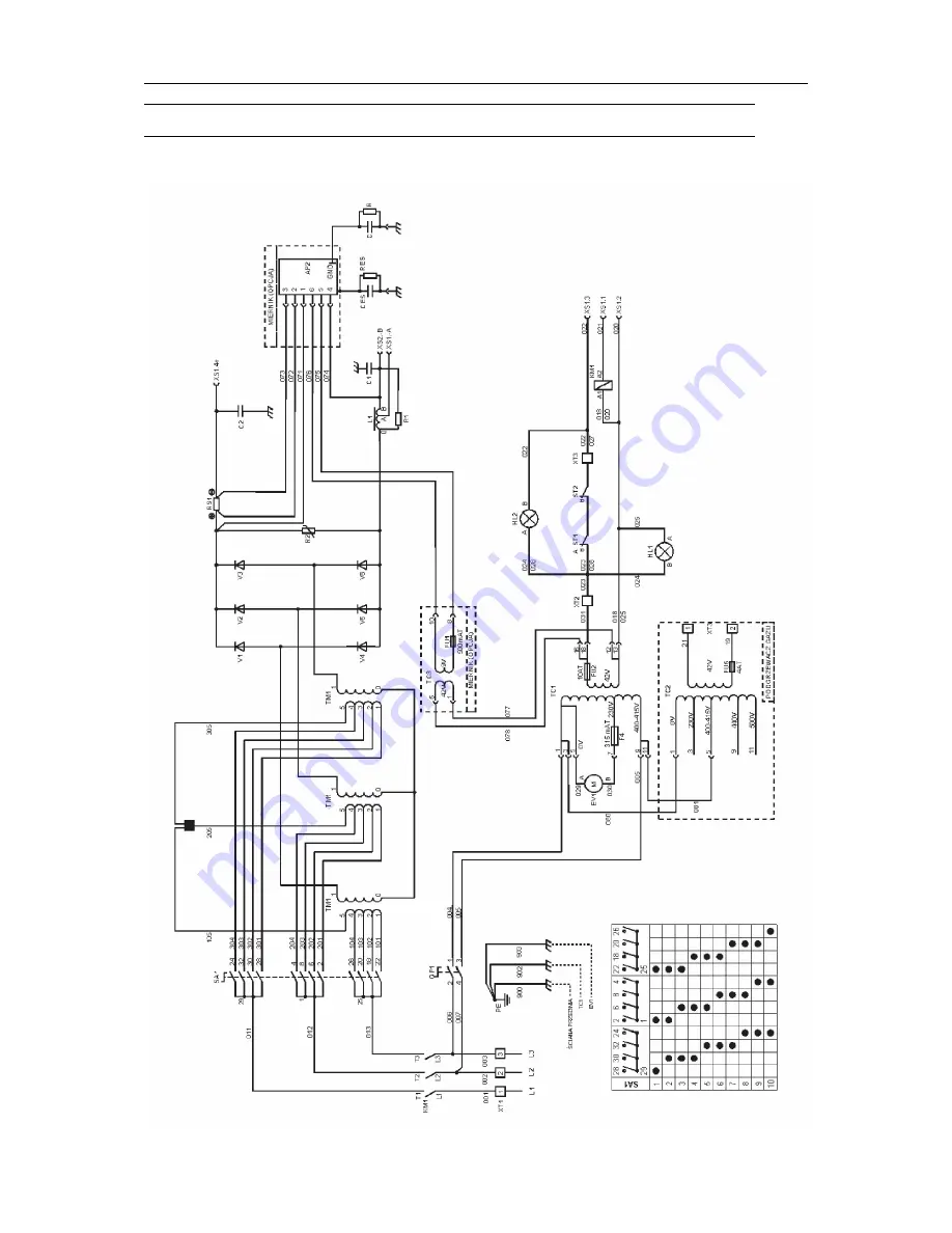
DIAGRAM

0349 301 124

- 21 -

© ESAB AB 2017

DIAGRAM

Origo

TM

Mig L305, 400-415 V

Summary of Contents for Origo Mig L305

Page 1: ...Origo Instruction manual 0349 301 124 GB 20170310 Valid for serial no 628 647 211 xxx xxxx Mig L305 Mig L405 ...

Page 2: ......

Page 3: ...lance 9 4 3 Assembly of components 10 4 4 Electrical installation 11 4 5 Mains power supply 12 5 OPERATION 14 5 1 Connection and control devices 14 5 2 Overheating protection 15 5 3 Inductance connection 15 6 MAINTENANCE 16 6 1 Inspection and cleaning 16 6 2 Topping up the coolant 16 7 TROUBLESHOOTING 18 8 ORDERING SPARE PARTS 19 CLEANING 20 DIAGRAM 21 ORDERING NUMBERS 24 ACCESSORIES 25 Rights res...

Page 4: ...ty precautions must meet the requirements that apply to this type of equipment The following recommendations should be observed in addition to the standard regulations that apply to the workplace All work must be carried out by trained personnel well acquainted with the operation of the equipment Incorrect operation of the equipment may lead to hazardous situations which can result in injury to th...

Page 5: ... ELECTRIC AND MAGNETIC FIELDS Can be dangerous to health Welders having pacemakers should consult their physician before welding EMF may interfere with some pacemakers Exposure to EMF may have other health effects which are unknown Welders should use the following procedures to minimize exposure to EMF Route the electrode and work cables together on the same side of your body Secure them with tape...

Page 6: ...quipment is not intended for use in residential locations where the electrical power is provided by the public low voltage supply system There may be potential difficulties in ensuring electromagnetic compatibility of class A equipment in those locations due to conducted as well as radiated disturbances NOTE Dispose of electronic equipment at the recycling facility In observance of European Direct...

Page 7: ...ed and equipped with thermal overload protection They can be fitted with an instrument that displays current and voltage It incorporates a hold function and can be calibrated ESAB accessories for the product can be found in the ACCESSORIES chapter of this manual 2 1 Equipment The power source is supplied with Return cable 5 m L305 3 5 m with clamp Shelf for gas cylinder Guide pin for wire feed uni...

Page 8: ...2 V 50 60 Hz 42 V 50 60 Hz Dimensions lxwxh 782 x 425 x 830 812 x 552 x 925 812 x 552 x 925 Weight 89 kg 142 kg 143 kg with cooling unit 156 kg 156 kg Operating temperature 10 to 40 C 10 to 40 C 10 to 40 C Transportation temperature 20 to 55 C 20 to 55 C 20 to 55 C Enclosure class IP 23 IP 23 IP 23 Application class Coolant ESAB ready mixed coolant Duty cycle The duty cycle refers to the time as a...

Page 9: ...sed when lifting the power source The handle is only intended for pulling it 4 1 Positioning of welding power source Position the welding power source in such a way that its cooling air inlets and outlets are not obstructed 4 2 Assembly of counter balance Assemble the stabilizer CB KIT if the counter balance is to be installed on the power source The stabilizer CB KIT is an accessory See ACCESORIE...

Page 10: ...TALLATION 0349 301 124 10 ESAB AB 2017 4 3 Assembly of components WARNING During transport the rear wheels of the power source are in their forward position Before use place the wheels in their rear position ...

Page 11: ...4 INSTALLATION 0349 301 124 11 ESAB AB 2017 4 4 Electrical installation ...

Page 12: ...A protective earth connection must be made in accordance with regulations Rating plate with supply connection data Recommended fuse sizes and minimum cable areas L305 3 50 60 Hz Voltage V 400 415 Current A at 100 duty cycle 7 at 60 duty cycle 10 at 25 duty cycle 18 Cable area mm2 4 x 2 5 Fuse slow A 16 L405 3 50 Hz 3 50 60 Hz 3 50 Hz 3 60 Hz 3 60 Hz Voltage V 203 400 415 500 230 440 460 Current A ...

Page 13: ...ycle 42 24 19 41 21 at 50 duty cycle 45 28 20 45 22 Cable area mm2 4 x 6 4 x 2 5 4 x 2 5 4 x 6 4 x 2 5 Fuse slow A 25 20 20 25 20 NOTE The mains cable areas and fuse sizes as shown above are in accordance with Swedish regulations For other regions supply cables must be suitable for the application and meet local and national regulations ...

Page 14: ...h 8 Connection for return cable high inductance 2 Main supply switch for cooling unit 9 Connection for return cable low inductance 3 Switch precise control 10 Connection for welding current cable 4 Switch coarse control 11 Connection for control cable for wire feeder 5 Indicating lamp power supply ON 12 Connection RED for cooling water from the wire feed unit 6 Orange indicating lamp overheating 1...

Page 15: ...hermal overload cutout protects against overheating The cutout resets automatically when the unit has cooled 5 3 Inductance connection Higher inductance produces a more flowing weld and fewer spatters Lower inductance produces a harsher sound and a stable concentrated arc ...

Page 16: ...duced pressure see CLEANING chapter This should be done more frequently in dirty environments Otherwise the air inlet outlet may become blocked and cause overheating To avoid this you can use an air filter 6 2 Topping up the coolant ESAB ready mixed coolant is recommended for use See ACCESSORIES chapter Fill with coolant The fluid level must not exceed the upper marking but neither must it be belo...

Page 17: ...6 MAINTENANCE 0349 301 124 17 ESAB AB 2017 CAUTION The coolant must be handled as chemical waste ...

Page 18: ...current is interrupted during welding Check whether the thermal overload trip has operated indicated by the orange lamp on the front Check the main power supply fuses Thermal overload trips operate frequently Check to see whether the air inlets outlets are clogged Make sure that you are not exceeding the rated data for the power source i e that the unit is not being overloaded Poor welding perform...

Page 19: ...nd European standards 60974 1 and 60974 10 It is the obligation of the service unit which has carried out the service or repair work to make sure that the product still conforms to the mentioned standard Spare parts and wear parts can be ordered through your nearest ESAB dealer see the back cover of this document When ordering please state product type serial number designation and spare part numb...

Page 20: ...CLEANING 0349 301 124 20 ESAB AB 2017 CLEANING ...

Page 21: ...DIAGRAM 0349 301 124 21 ESAB AB 2017 DIAGRAM OrigoTM Mig L305 400 415 V ...

Page 22: ...DIAGRAM 0349 301 124 22 ESAB AB 2017 OrigoTM Mig L405 400 415 V ...

Page 23: ...DIAGRAM 0349 301 124 23 ESAB AB 2017 OrigoTM Mig L405 230 500 V ...

Page 24: ... 0349 306 517 Origo Mig L405 400 415 V 3 50 Hz 0349 306 594 Origo Mig L405 230 400 415 500 V 3 50 Hz 230 440 460 V 3 60 Hz 0349 306 563 Origo Mig L405w 400 415 V 3 50 Hz 0349 306 595 Origo Mig L405w 230 400 415 500 V 3 50 Hz 230 440 460 V 3 60 Hz 0349 313 090 Origo Mig L405 400 415 V 3 50 Hz with digital instrument Technical documentation is available on the Internet at www esab com ...

Page 25: ...ESAB AB 2017 ACCESSORIES 0459 495 782 OrigoTM Feed L302 open 0459 495 882 OrigoTM Feed L304 open 0349 302 451 0349 302 598 Digital meter L405 Digital meter L305 0349 302 250 Transformer kit for CO2 heater 0349 303 362 Cable holder ...

Page 26: ...only L405 CONTAINS KIT for Counter Balance 0349 309 748 Stabilizer 0349 303 474 0349 309 471 Fan speed reductor L405 0465 720 002 ESAB ready mixed coolant 10 l 2 64 gal Use of any other cooling liquid than the prescribed one might damage the equipment In case of such damage all warranty undertakings from ESAB cease to apply ...

Page 27: ...ACCESSORIES 0349 301 124 27 ESAB AB 2017 ...

Page 28: ...e Henares MADRID Tel 34 91 878 3600 Fax 34 91 802 3461 SWEDEN ESAB Sverige AB Gothenburg Tel 46 31 50 95 00 Fax 46 31 50 92 22 ESAB International AB Gothenburg Tel 46 31 50 90 00 Fax 46 31 50 93 60 SWITZERLAND ESAB Europe GmbH Baar Tel 41 1 741 25 25 Fax 41 1 740 30 55 UKRAINE ESAB Ukraine LLC Kiev Tel 38 044 501 23 24 Fax 38 044 575 21 88 North and South America ARGENTINA CONARCO Buenos Aires Tel...

Reviews: