


17
onto the non-inverting input of A14d comparator. In the AG mode, the ANTISTICK function is switched
off by means of shorting the A14b comparator output with the activated output transistor of the A14a
comparator.
The HOT START function is carried out by A15 and D1 integrated circuits. When the welding starts
and the arc ignition takes place, V
94
transistor is switched on, which results in the high level on the
A15a amplifier output. The C
61
capacitor is charged via the R
197
resistor. The charging time of this
capacitor up to the voltage set by the HOT START potentiometer and sent to the non-inverting input of
A15b amplifier defines the HOT START operating time. As long as the voltage on the C
61
capacitor is
lower than the voltage set with the HOT START potentiometer, the level at the A15b output is high,
while the D1a circuit output transistor connects the R
173
resistor to the ground. Connecting the resistor
to the ground will result in the rise of voltage by 50% on the A16a operational amplifier output with
reference to the voltage at the non-inverting input, thus increasing the welding current setting value.
The HOT START function is blocked in the TIG mode. It is also deactivated if the HOT START
potentiometer is set to the minimum value.
The ARC FORCE function is carried out by the A16 operational amplifier. After reducing the initial
voltage to the value below the threshold of activating the ARC FORCE function, voltage on the A16b
output is decreasing. Reduction of this voltage results in the increase of the amount of current flowing
through the V
97
transistor and the increase of voltage at the A16a output, thus increasing the value of
the welding current. Maximum increase in the value of the welding current accompanying the arc
shortening may be regulated using the ARC FORCE potentiometer.
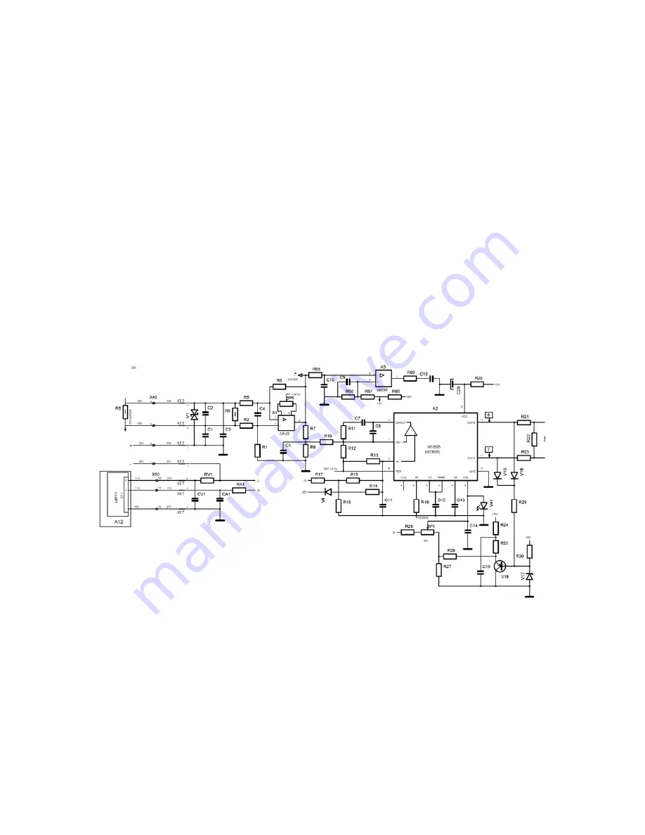
Current loop control system
Feedback signal from the shunt is amplified 100x by means of a differential amplifier made on the A1
operational amplifier and R
1
, R
2
, R
5
, R
6
resistors. Next, by means of R
7
, R
8
, R
10
resistors it is carried
onto the input of the PI type regulator made on the operational amplifier included in the A2 integrated
circuit. Voltage signal proportional to the welding current is transmitted onto the non-inverting input of
this amplifier via R
17
, R
16
, R
15
resistors. Output voltage from the PI regulator controls the operation of
the PWM modulator included in the A2 integrated circuit. Operation of the PWM modulator may be
blocked by means of a low logical level of a signal on the V
4
diode cathode, coming from the
protecting systems (thermal, lack of liquid circulation, too low supply voltage) and from the source
switch on/off control system. The electronic circuit made on the V
19
transistor is the limiter of the
maximum current source. The value of the current is set using the RP1 potentiometer. The PWM
output signal controls diodes of the VC
5
transoptor located in the driver circuit.
Summary of Contents for Origo Arc 410c
Page 6: ...5...
Page 8: ...7 OrigoTM Arc 410c...
Page 9: ...8 OrigoTM Arc 650c...
Page 10: ...9 OrigoTM Arc 810c...
Page 15: ...14 LM11 Component positions...
Page 22: ...21 CH21 Component positions...
Page 23: ...22 K69 Suppression circuit board Circuit diagram Component positions...
Page 38: ...37 NOTES...
Page 39: ......


