


16
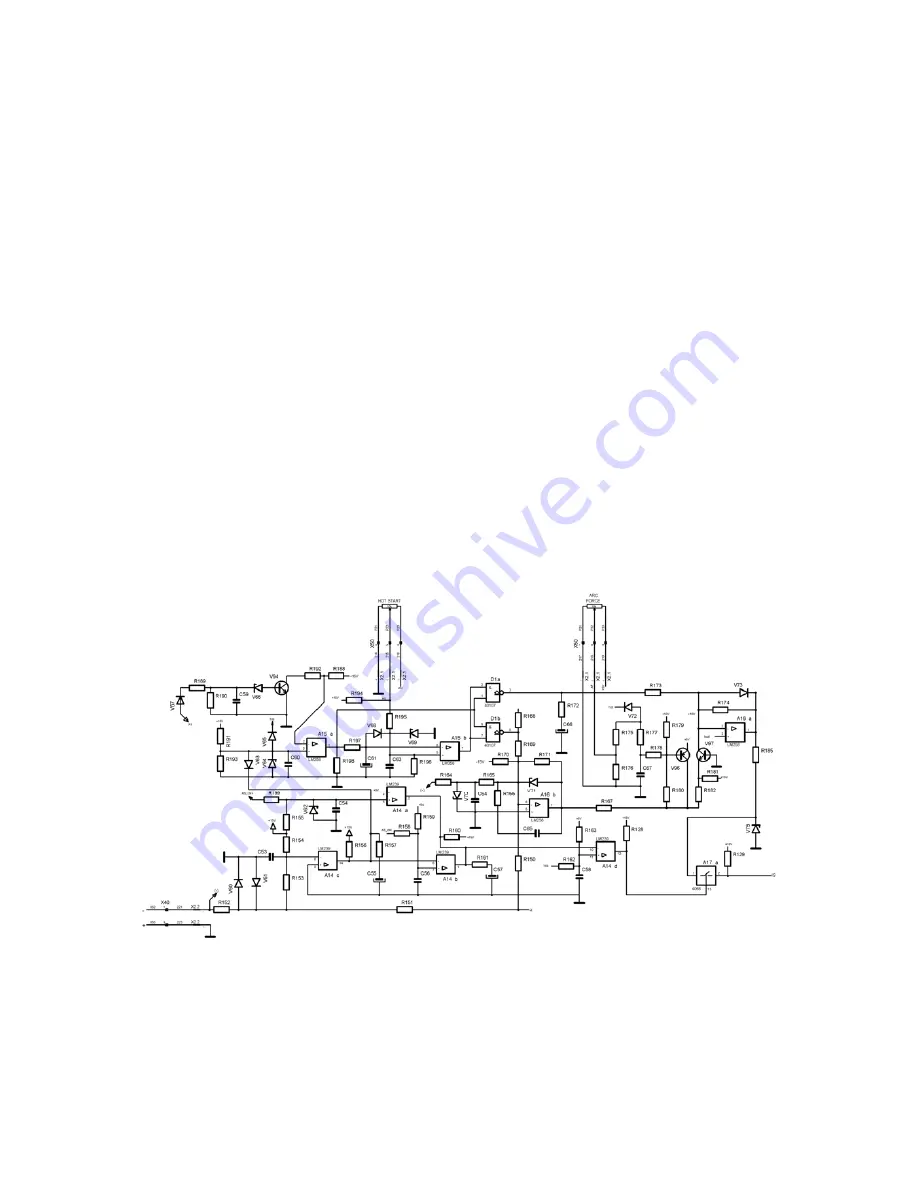
Switching to the remote wire supply mode is performed automatically after fixing the peripheral device
to the X01 socket on the cap board of the device. The electronic system of remote setting is
galvanically separated from the remaining electronic circuits controlling the source operation.
The VC
2
transoptor carries a signal which switches off the A17c key and switches on the A17d key,
transmitting the signal from the A12b amplifier output onto the A13d separating follower input, thus
activating the remote setting. The VC
2
transoptor transmits the signal of the welding current value.
This is a signal with a variable pulse-duty factor for a rectangular wave, proportional to the value set by
the potentiometer on the remote regulation peripheral device. The circuit made of the A11a
comparator and V
55
transistor generates the signal. The A11b comparator disables the generator if the
remote regulation peripheral device is disconnected from the device. Elements VB
1
, C
41
, R
114
, R
115
,
R
116
, V
50
, V
51
, V
52
, V
53
, C
42
and C
43
make up the power unit for the galvanically separated part of the
remote setting circuit. The rectangular wave of the stable voltage amplitude and of time parameters
depending on the set welding current is obtained on the V
57
transistor collector. This signal is
averaged by means of a low-pass filter made on the A12a operational amplifier. The function of the
circuit made on the A12b operational amplifier is to set the changes range of the voltage setting the
welding current. The RP
2
potentiometer is used for resetting the setting signal for the current setting
potentiometer on the peripheral device to the minimum value. R
114
potentiometer is designed for
setting the maximum value of the setting signal for the current setting potentiometer on the peripheral
device to the maximum value. Calibration procedure is described in detail in item 2 – Procedures for
checking and calibration of the source. The A13d follower output is connected to the R
184
resistor and
RP
4
potentiometer used for calibrating the maximum welding current in MMA, AG and TIG methods.
An amplifier with amplification 2 is made on the A13c operational amplifier. Potentiometers R
114
and
RP
2
are connected to the output of this amplifier. The RP
5
potentiometer sets the minimum current. I
sol
voltage signal is the current setting in MMA, AG and TIG methods and it is transmitted onto the non-
inverting input of the A16a amplifier.
ANTISTIC, HOTSTART, ARC FORCE functions
The ANTISTICK function is carried out by the A14 integrated circuit.In the event that the electrode
sticks and the welding voltage is reduced to the value below the threshold of activating the ANTISTICK
function, the transistor in the A14c compactor is closed, which results in a delayed closure of the
transistor in A14d comparator. Closing this transistor will result in opening the A17a key and in
reduction of the voltage of the welding current setting I
s
to the minimum value, thus reducing the
output current of the source. In the MMA mode, the C
57
capacitor and R
160
+ R
161
resistors are
responsible for the delay of the ANTISTICK function activation. In the TIG mode, the delay of the
ANTISTICK function activation is switched off by means of a TIG signal transmitted by the R
162
resistor
Summary of Contents for Origo Arc 410c
Page 6: ...5...
Page 8: ...7 OrigoTM Arc 410c...
Page 9: ...8 OrigoTM Arc 650c...
Page 10: ...9 OrigoTM Arc 810c...
Page 15: ...14 LM11 Component positions...
Page 22: ...21 CH21 Component positions...
Page 23: ...22 K69 Suppression circuit board Circuit diagram Component positions...
Page 38: ...37 NOTES...
Page 39: ......


