ESAB Migmaster 300i cvcc Service And Maintenance Manual Download Page 5

5

FUMES AND GASES -- Fumes and
gases, can cause discomfort or harm,
particularly in confined spaces. Do
not breathe fumes and gases. Shield-
ing gases can cause asphyxiation.
Therefore:

1. Always provide adequate ventilation in the work area by

natural or mechanical means. Do not weld, cut, or gouge
on materials such as galvanized steel, stainless steel,
copper, zinc, lead, beryllium, or cadmium unless posi-
tive mechanical ventilation is provided. Do not breathe
fumes from these materials.

2. Do not operate near degreasing and spraying opera-

tions. The heat or arc rays can react with chlorinated
hydrocarbon  vapors to form phosgene, a highly toxic
gas, and other irritant gases.

3. If you develop momentary eye, nose, or throat irritation

while operating, this is an indication that ventilation is not
adequate. Stop work and take necessary steps to im-
prove ventilation in the work area. Do not continue to
operate if physical discomfort persists.

4. Refer to ANSI/ASC Standard Z49.1 (see listing below)

for specific ventilation recommendations.

5. WARNING: This product, when used for welding or

cutting, produces fumes or gases which
contain chemicals known to the State of
California to cause birth defects  and, in
some cases, cancer. (California Health &

Safety Code 

§

25249.5 et seq.)

CYLINDER HANDLING -- Cylinders, if
mishandled, can rupture and violently
release gas. Sudden rupture of cylin-
der, valve, or relief device can injure or
kill. Therefore:

1. Use the proper gas for the process and use the proper

pressure reducing regulator designed to operate from
the compressed gas cylinder. Do not use adaptors.
Maintain hoses and fittings in good condition. Follow
manufacturer's operating instructions for mounting regu-
lator to a compressed gas cylinder.

2. Always secure cylinders in an upright position by chain

or strap to suitable hand trucks, undercarriages, benches,
walls, post, or racks. Never secure cylinders to work
tables or fixtures where they may become part of an
electrical circuit.

3. When not in use, keep cylinder valves closed. Have

valve protection cap in place if regulator is not con-
nected. Secure and move cylinders by using suitable
hand trucks. Avoid rough handling of cylinders.

4. Locate cylinders away from heat, sparks, and flames.

Never strike an arc on a cylinder.

5. For additional information, refer to CGA Standard P-1,

"Precautions for Safe Handling of Compressed Gases in
Cylinders", which is available from Compressed Gas
Association, 1235 Jefferson Davis Highway, Arlington,
VA 22202.

EQUIPMENT MAINTENANCE -- Faulty or
improperly maintained equipment can
cause injury or death. Therefore:

1. Always have qualified personnel perform the installa-

tion, troubleshooting, and maintenance work. Do not
perform any electrical work unless you are qualified to
perform such work.

2. Before performing any maintenance work inside a power

source, disconnect the power source from the incoming
electrical power.

3. Maintain cables, grounding wire, connections, power

cord, and power supply in safe working order. Do not
operate any equipment in faulty condition.

4. Do not abuse any equipment or accessories.  Keep

equipment away from heat sources such as furnaces,
wet conditions such as water puddles, oil or grease,
corrosive atmospheres and inclement weather.

5. Keep all safety devices and cabinet covers in position

and in good repair.

6. Use equipment only for its intended purpose. Do not

modify it in any manner.

ADDITIONAL SAFETY INFORMATION -- For
more information on safe practices for elec-
tric arc welding and cutting equipment, ask
your supplier for a copy of "Precautions and
Safe Practices for Arc Welding,  Cutting and
Gouging", Form 52-529.

The following publications, which are available from the
American Welding Society, 550 N.W. LeJuene Road, Mi-
ami, FL 33126, are recommended to you:
1. ANSI/ASC Z49.1 - "Safety in Welding and Cutting"
2. AWS C5.1 - "Recommended Practices for Plasma Arc

Welding"

3. AWS C5.2 - "Recommended Practices for Plasma Arc

Cutting"

4. AWS C5.3 - "Recommended Practices for Air Carbon

Arc Gouging and Cutting"

5. AWS C5.5 - "Recommended Practices for Gas Tungsten

Arc Welding“

6. AWS C5.6 - "Recommended Practices for Gas Metal Arc

Welding"“

7. AWS SP - "Safe Practices" - Reprint, Welding Hand-

book.

8. ANSI/AWS F4.1, "Recommended Safe Practices for

Welding and Cutting of Containers That Have Held
Hazardous Substances."

MEANING OF SYMBOLS - As used through-
out this manual: Means Attention! Be Alert!
Your safety is involved.

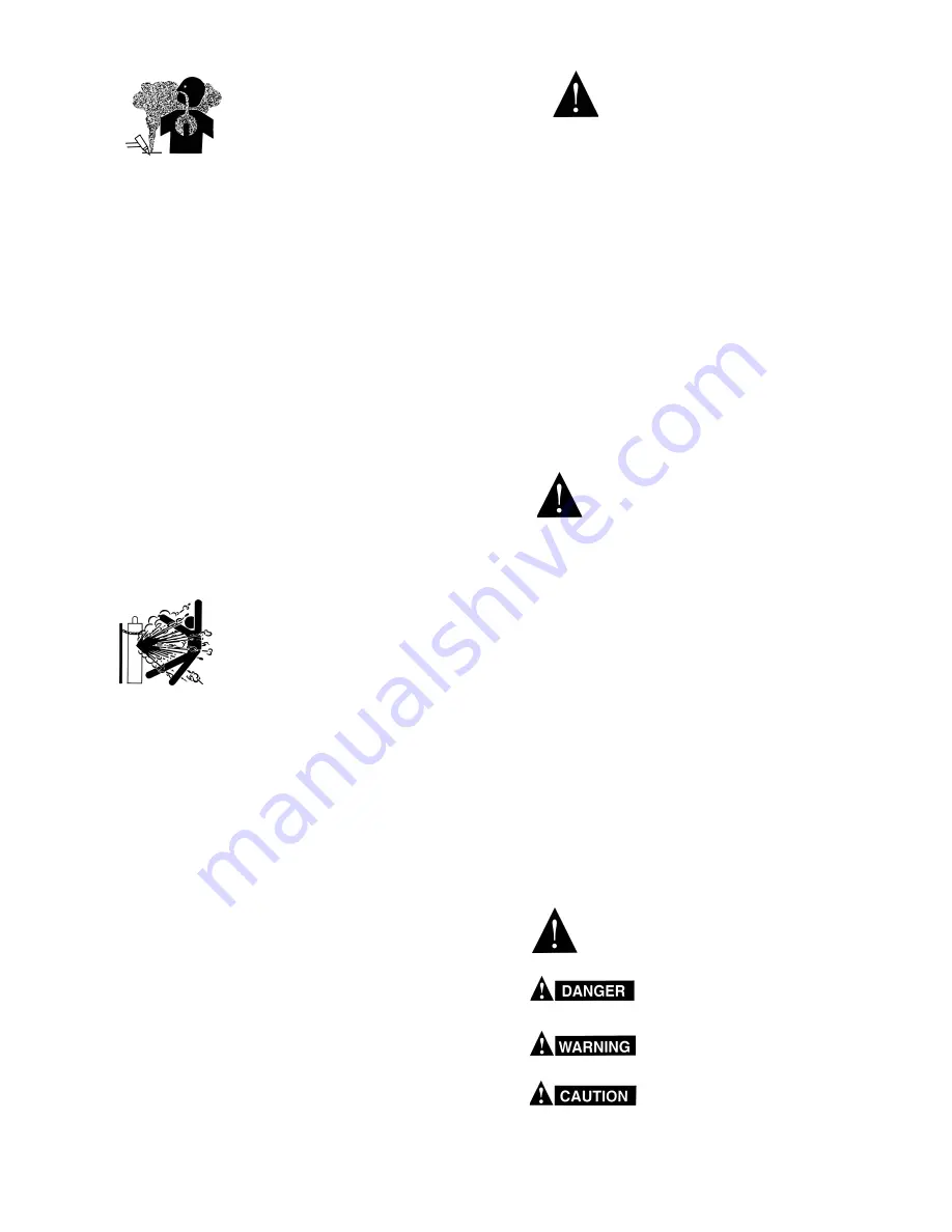
Means immediate hazards which, if
not avoided, will result in immediate,
serious personal injury or loss of life.

Means potential hazards which could
result in personal injury or loss of life.

Means hazards which could result in
minor personal injury.

SP98-10

Summary of Contents for Migmaster 300i cvcc

Page 1: ...Migmaster 300i cvcc WELDING POWER SUPPLY SERVICE AND MAINTENANCE BEFORE SERVICING READ AND COMPLY WITH THESE INSTRUCTIONS F 15 097 A March 2001...

Page 2: ...Finding Welding Parameters in MIG 12 3 5 Synergic Relationships and Functions 12 3 6 Servo Functions 12 3 7 Saving Welding Conditions 13 3 8 Fault Conditions 13 IV INSTALLATION OF POWER SOURCE AND AC...

Page 3: ...1 Stick Welding 22 5 3 2 TIG Welding 24 5 3 3 MIG Welding 24 5 3 3 1 Guided Mode of Setting Welding Parameters 24 5 3 3 2 Manual Mode of Setting Welding Parameters 24 5 4 Description of Trigger Type...

Page 4: ...on the workpiece which might pro duce flammable or toxic vapors Do not do hot work on closed containers They may explode 4 Have fire extinguishing equipment handy for instant use such as a garden hose...

Page 5: ...Never strike an arc on a cylinder 5 For additional information refer to CGA Standard P 1 Precautions for Safe Handling of Compressed Gases in Cylinders which is available from Compressed Gas Associati...

Page 6: ...nt Any claims for loss or damage occurring in transit must be filed with the carrier The carrier will furnish a copy of the bill of lading and the freight bill on request if the need to file a damage...

Page 7: ...023 030 and 034 045 regulator and adjustable flowmeter 10 gas hose 10 work cable and clamp 10 primary cable with plug and receptacle and Welding Handbooks Description Part Number Migmaster 300i cvcc...

Page 8: ...237 17718 2075238 052 1 4mm 948340 2075349 2075239 17719 2075240 1 16 1 6mm 948341 996997 2075239 17719 2075240 Soft Wires aluminum 035 9mm 996995 996996 948862 3 64 999578 996999 996998 948863 Wire S...

Page 9: ...zle Desc I D Standard Duty Heavy Duty 6 Tapered 3 8 998895 8 1 2 998893 999471 10 5 8 998894 999472 12 3 4 999473 12 Spot 3 4 17316 999625 10 Stud 5 8 17173 Uses Nozzles Adapter P N 999452 2 6 SAFETY...

Page 10: ...i cvcc Power Source Informa tion contained in this manual should be read carefully before performing service or maintenance tasks 3 2 POWER SOURCE The Power Source consists of three main components A...

Page 11: ...s selected are present in the list If SEL SET UP TYPE is guided mode you will find lines in the list that will allow the operator to specify wire type wire size shield ing gas plate size voltage trim...

Page 12: ...g param eters The wire speed and welding voltage is preset by the control unit as a function of the chosen consumables and material size Setting of the plate thickness will have the same effect as a c...

Page 13: ...hat the problem is in the following manner A Top row shows DETECTED A FAULT B Bottom row indicates the problem It may be difficult to see the message on occasion due to the function of the screen disp...

Page 14: ...assemblybyinsertingapinintoeachendofthe axle C Remove the existing shipping supports by un screwing from chassis 4 3 ELECTRICAL INPUT CONNECTIONS In order to provide a safe and convenient means to co...

Page 15: ...ARY OUTPUT CONNECTIONS The Migmaster 300i Power Source is completely self contained so that the front panel torch fittings are in ternally connected to the welding polarity dc reverse or dc straight v...

Page 16: ...ipment is to a large extent dependent on the use of welding cables and connections which are in good condition and of ad equate size 4 6 INSTALLATION FOR MIG WELDING BE SURE THE BRANCH CIRCUIT OR MAIN...

Page 17: ...4 6 3 3 THREADING WELDING WIRE A Turn off power switch WHEN THE POWER SWITCH IS ON AND GUN TRIGGER IS DEPRESSED THE ELECTRODE WIRE BECOMES ELECTRICALLY HOT AND THE WIRE FEED ROLLS ARE ACTIVATED B Rel...

Page 18: ...1 1 8in openendwrenchoranadjustablewrench To prevent damaging the O ring seals and plastic tube do not use the flowmeter tube as a handle when attaching the regulator Figure 4 6 R 50 Regulator C Make...

Page 19: ...CHING WORKPIECE WHEN INITIALLYAPPLYING POWER BE SURE THAT GAS CYLINDER VALVE IS CLOSED TO PREVENT GAS FROM BEING PRESENT WHEN INITIALLY APPLYING POWER The Migmaster 300i Power Source is not designed f...

Page 20: ...to the ELEC TRODE negative output receptacle J6 and the plug of the Work lead to the ELECTRODE positive out put receptacle J5 Refer to Section V for operational instructions NOTE The TIG or MIG Torch...

Page 21: ...the helmet is lowered over the face the opera tor should wear flash goggles with filter lenses underhishelmet Thehelmetfilterplateshould be shade number 11 nonferrous or 12 fer rous All those viewing...

Page 22: ...or wire speed for desired arc characteristics These changes can be made while welding NOTE Make small changes when fine tuning the arc Too large a change will make the arc unstable When entering setup...

Page 23: ...increase PRE FLOW or to decrease PRE FLOW Use to increase POST FLOW or to decrease POST FLOW Table 5 1 Migmaster 300i cvcc STICK Process Display Action Connect electrode holder and Work lead Select S...

Page 24: ...rce 1 manual mode and 2 guided mode Both modes will be briefly explained here For detailed explanation refer to Section III paragraph 3 3 The selection is made when SEL SET UP TYPE ap pears The bottom...

Page 25: ...switch Power on unit Set shielding gas flowmeter to 35 cfh Use or to change WIRE TYPE to desired material Note Wire Type Options are listed in Table 4 3 Use or to change WIRE SIZE to desired diameter...

Page 26: ...e WIRE SIZE Press or to change GAS SHIELD mixture Press or to change TRIGGER TYPE COMMENT Active lists options active list 1 active list 2 active list 3 Set up options guided set up manual set up Wire...

Page 27: ...ase WIRE SPEED Press to decrease WIRE SPEED Press to increase VOLTAGE Press todecreaseVOLTAGE Table 5 4 Migmaster 300i cvcc SET UP OPTIONS for The MIG Process Cont COMMENT This option appears when TRI...

Page 28: ...ART TYPE Press or to trim BURNBACK time Press or to trim WIRE SPEED Press or to TRIM VOLT AGE Press to increase PLATE SIZE Press to decrease PLATE SIZE COMMENT This display appears on manual set up on...

Page 29: ...the guided set up is shown Use and to set wire feed speed Use and to set welding voltage Use and to set inductance percentage Use and to select TRIGGER TYPE Note Trigger Type options are listed in Tab...

Page 30: ...ble 4 3 Use or to set BURNBACK time if needed Display SEL START TYPE normal TRIM BURNBACK v 0 20 seconds The shaded boxes are the only settings required to be changed by the operator to find the weldi...

Page 31: ...duration Once the torch switch is pressed the option with the spot time is moved up in the list to be quickly accessible to locate the parameters for the spot welding operation D Stitch Welding Stitc...

Page 32: ...art method is called slow run in and may be selected when SEL START TYPE appears The other selection is normal This gives starts with the wire feed speed used during welding Refer to Table 5 7 for SEL...

Page 33: ...hazards IF UNINSULATED CABLE AND PARTS ARE NOT REPLACED AN ARC CAUSED BYA BARED CABLE OR PART TOUCHINGA GROUNDED SURFACE MAY DAMAGE UNPROTECTED EYES OR STARTA FIRE BODYCONTACT WITH A BARED CABLE CONN...

Page 34: ...d on the wire compartment shelf ac cessible from the wire feeder compartment Failure of this circuit breaker will shut off the contactor shielding gas and wire feeder 6 2 1 5 OVER TEMPERATURE PRO TECT...

Page 35: ...ned wir ing or components or any other sign of damage or discoloration VII TROUBLESHOOTING AND REPAIR 7 1 TROUBLESHOOTING If welding equipment doesn t work right despite com pliance with checklist ins...

Page 36: ...correct polarity 5 Welding output voltage a Low line voltage a Use correct voltage and or current too low b Welding cables too long or too b Use correct cable size small c Loose connection c Check all...

Page 37: ...ust setting f Drive or pressure roll dirty or f Clean rolls or replace worn 13 Wire does not feed a Kink etc in wire or wire bound a Straighten or feed wire until motor running drive on reel clear and...

Page 38: ...38...

Page 39: ...39...

Page 40: ...40...

Page 41: ...is recommended that only genuine ESAB parts and products be used with this equipment The use of non ESAB parts may void your warranty Replacement parts may be ordered from your ESAB distributor For a...

Page 42: ...80359 951261 993952 33619YL 32135GY 32995 950396 33620YL 954202 13730912 13735895 33291YL 2091514 33616GY ASSEMBLY LCD 16 CHARACTERS 15 COND KEYPAD MEMBRANE SWITCH 3 POS RECEPTACLE 2 POLE HIDDEN RECEP...

Page 43: ...REAR VIEW ITEM NO QTY REQ PART NO DESCRIPTION CKT DESIG 1 2 3 4 5 6 1 1 1 1 1 14 FT 13736731 678944 08030255 08030245 33613 95195024 BRACKET CYLINDER CHAIN 36 IN NUT HOSE CONNECTION CONNECTION HOSE 3...

Page 44: ...44 2 3 4 5 6 7 8 9 10 11 12 13 14 15 16 17 18 19 20 21 1 22 23 24 25 26 27 28 29 FIGURE 8 2 MIGMASTER 300i LEFT INTERIOR VIEW...

Page 45: ...G 9 POS CONNECTOR BODY RECEPTACLE 9 POS SHELF EXTENSION PAD THERMAL DIODE MODULE RECTIFIER OUTPUT CAPACITOR 05 uF 500 V RESISTOR 5 OHM 50 W CONNECTOR NO 2 1 0 AWG CURRENT TRANSFORMER SWITCH THERMAL 80...

Page 46: ...46 2 3 4 5 6 7 8 9 10 11 12 13 14 15 1 16 17 18 19 20 21 FIGURE 8 3 MIGMASTER 300i RIGHT INTERIOR VIEW...

Page 47: ...8950248 33344 33345 33343 17250110 13733935 13792051 23610528 23610696 23612350 92047075 23612590 21165 MOTOR GEAR DRIVE STAND ASSY GUIDE TUBE INLET SHELF WIRE COMPARTMENT NUT SUPPORT REEL HUB REEL CA...

Page 48: ...pair Stations C TECHNICAL SERVICE Telephone 800 ESAB 123 Fax 843 664 4452 Part Numbers Technical Applications Hours 8 00 AM to 5 00 PM EST Performance Features Technical Specifications Equipment Recom...

Reviews: