11
3.3.2 OPERATIONAL DESCRIPTION OF DISPLAY
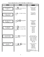
The display screen presents a two-line alphanumeric
display. The upper line displays the main control func-
tion and the lower line displays the selections and set-
tings made. Additionally, the upper line indicates mea-
sured data during welding and holds this data until
changed by the keypads.
The right and left keypads are used to increase and
decrease the setting of parameters. The arrow point-
ing up on the right keypad indicates an increase in pa-
rameter value while the arrow pointing down on the left
keypad indicates a decrease in parameter value.
The keypads are also used to select between different
choices. For this operation, the right keypad selects
choices to the right as indicated by the arrow. Like-
wise, the left keypad will select choices to the left as
indicated by the arrow. The middle keypad is used to
step to the next line in a list to be changed.
Finding and setting a welding condition is an iterative
process. This means that one or more parameters
are tuned to reach a desired result. Tuning means
that the value of a parameter is changed, a test weld is
performed, and based upon the test weld results, the
operator will either change the setting or select another
parameter to tune. This process continues until a sat-
isfactory welding condition for the job is found.
To make this process effective with as few controls as
possible, all parameters are stored in a dynamic list.
The order of the parameter list is based upon whether
or not the value is changed. This will always keep the
most likely parameter to be changed accessible and
the second most likely parameter to be the next pa-
rameter to be accessed. Changing a parameter will
put that parameter line on top of the list. Not changing
the parameter will leave it in its position. This applies
only to MIG set parameters such as voltage, wire feed
speed, inductance, spot time, etc. In this way, the it-
erative process of finding a set of welding parameters
will be accelerated.
To limit the number of lines in the list, only those items
selected are present in the list. If SEL SET-UP TYPE
is "guided mode" you will find lines in the list that will
allow the operator to specify wire type, wire size, shield-
ing gas, plate size, voltage trim, and wire speed. If
"manual mode" is selected, SEL SET-UP TYPE will
disappear and the operator will find lines allowing the
setting of voltage, wire feed speed, and inductance.
When the operator starts to weld or hits the torch switch,
the top of the list is displayed. An overview of the total
setting is made by stepping down the parameter list.
(It is only possible to step down the list and set or se-
lect.) Notes may be made in the free space of the
front panel.
3.3.3 OPERATIONAL PROCEDURE OF DISPLAY
A. The upper line shows the main control func-
tion; SELect an item or SET a parameter.
B. The middle keypad advances the display to the
next line of parameters in the list. The bottom
line shows the present (active) SELection or
SETting. If this is satisfactory, and another
item is desired, press the middle keypad again.
C. If the left or right keypad is pressed, the
SELection is changed. A SET value of a
parameter is set by pressing the left (decrease)
or right (increase) keypad again. One of the
following will occur the next time the middle
keypad is pressed:
1. If other lines are dependent on the
SELection made, they will appear the next
time the middle keypad is pressed.
2. A change of a parameter that the operator
SET will put that parameter at the top of
this list the next time the middle keypad is
pressed and the list will move down a line.
The next line will be displayed (not the
second in the list). If the torch switch is
pressed instead of the middle keypad, the
changed parameter at the top of the list
will be displayed.
D. When the torch switch is pressed and/or weld-
ing starts, the display's lower line shows the
last SET item. The upper line shows measured
data (normally current and voltage).
E. After welding, the upper line returns to the main
control function text when any of the three
keypads are pressed the first time.
F. If a SET parameter is in the lower line of the
display during welding, the left (decrease) and
right (increase) keypads may be used. The two
knobs on the torch or pendant may be used to
change the parameters since they have the
same function as the left and right keypads.


