13
3.7 SAVING WELDING CONDITIONS
If a job is to be repeated at a later time, it may be de-
sired to save the welding conditions just completed.
To make this possible, the MigMaster 300i has three
lists, each containing a complete MIG setup. One of
the three lists is always active. The line SEL ACTIVE
LIST shows which list is active. If the "active list #1"
shows on the lower line of the display while scrolling
through the list, it means that the whole list is list num-
ber one.
If the Power Source is set up for a job and the operator
desires to come back to these settings later, change
the active list to number 2 or 3 with the right keypad.
Now a new set of parameters can be set up for an-
other job. Returning to the parameters of the first job
is done by stepping through the list with the middle
keypad to the upper line of SEL ACTIVE LIST and us-
ing the left keypad to SELect "active list #1".
3.8 FAULT CONDITIONS
The operating parameters of the MIGMASTER 300i
Power Source is continuously monitored without inter-
fering with the operator. The control circuit monitors
the following:
A. Main input voltage for over or under voltage
conditions.
B. Thermal switches (TS1 and TS2) and power
output to prevent Power Source overheating.
C. Wire feeder motor (M2) speed.
D. Electrical function of the inverter power unit.
In the event the monitoring activity detects any out-of-
tolerance conditions, the operation in progress is inter-
rupted and the display indicates what the problem is in
the following manner:
A. Top row shows "DETECTED A FAULT".
B. Bottom row indicates the problem.
It may be difficult to see the message on occasion due
to the function of the screen displaying the measured
values of the current welding process. The informa-
tion is easy to find because it is a line in the list and
when the operator scrolls through the list, the mes-
sage line will show up as one of the lines in the list.
When the displayed problem(s) are corrected, the mes-
sage will disappear and operation may be resumed.
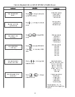
Table 3-1. Parameter Defaults
In MIG process:
Top row
Bottom row
SEL SET-UP TYPE
SEL WIRE TYPE
SEL WIRE SIZE
SEL GAS SHIELD
SEL PLATE SIZE
TRIM VOLTAGE
TRIM WIRE SPEED
SEL TRIGGER TYPE
SEL START TYPE
TRIM BURNBACK
SEL ACTIVE LIST
guided mode
mild steel
.035" dia.
90Ar+8C02+202
16ga .060"
14.8 +0.0 volts
125 +0ipm
continuous
normal
0.20 seconds
list #1
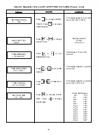
In TIG process:
Top row
Bottom row
SET CURRENT TIG
SET PRE FLOW
SET POST FLOW
60 amps
0.5 seconds
12.0 seconds
In STICK process:
Top row
Bottom row
0 Amp 51.0 Volts
STICK 120 amps
The only exception to this is the fault "high current". In
this case, the Power Source will have to be shut down
(off) and a service representative contacted.
If during welding, a short circuit (i.e., frozen electrode)
is maintained longer than normal, a safety function limits
the output. Once the short is removed, the operation
will return to normal.
To display the default settings, press the left and middle
keypad and turn power switch to ON (while holding
keypads down). This action will give the default set-
ting of the lists. The complete setting of all parameter
defaults are shown in Table 3-1.


