


ESAB FABRICATOR 211i
Manual 0-5450 3-7 SAFETY/INSTALLATION
3. Welding Cables
The welding cables should be kept as short as possible and should be positioned close together but never coiled and running
at or close to the floor level.
4. Equipotential Bonding
Bonding of all metallic components in the welding installation and adjacent to it should be considered. However, metallic
components bonded to the work piece will increase the risk that the operator could receive a shock by touching the metallic
components and the electrode at the same time. The operator should be insulated from all such bonded metallic components.
5. Earthing/grounding of the Work Piece
Where the work piece is not bonded to earth for electrical safety, nor connected to earth because of its size and position, e.g.
ship’s hull or building steelwork, a connection bonding the work piece to earth may reduce emissions in some, but not all
instances. Care should be taken to prevent the earthing of the work piece increasing the risk of injury to users, or damage
to other electrical equipment. Where necessary, the connection of the work piece to earth should be made by direct con-
nection to the work piece, but in some countries where direct connection is not permitted, the bonding should be achieved
by suitable capacitance, selected according to national regulations.
6. Screening and Shielding
Selective screening and shielding of other cables and equipment in the surrounding area may alleviate problems of interference.
Screening the entire welding installation may be considered for special applications.
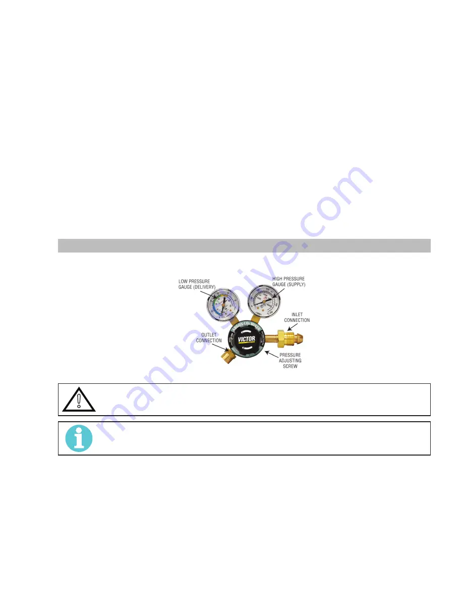
3.08 Victor Regulator
Pressure regulator (Figure 3-5) attached to the cylinder valve reduce high cylinder pressures to suitable low working pressures for
welding, cutting, and other applications.
A-09414_AC
Figure 3-5: Victor CS Regulator
!
WARNING
Use the regulator for the gas and pressure for which it is designed. NEVER alter a regulator for use with
any other gas.
NOTE!
Regulators purchased with open 1/8”, 1/4”, 3/8”, or 1/2” NPT ports must be assembled to their intended
system.
1. Note the maximum inlet pressure stamped on the regulator. DO NOT attach the regulator to a system that has a higher pres-
sure than the maximum rated pressure stamped on the regulator.
2. The regulator body will be stamped “IN” or “HP” at the inlet port. Attach the inlet port to the system supply pressure connec-
tion.
3. If gauges are to be attached to the regulator and the regu lator is stamped and listed by a third party (i.e. “UL” or “ETL”). The
following requirements must be met:
a) Inlet gauges over 1000 PSIG (6.87 mPa) shall conform with the requirements of UL 404, “Indicating Pressure Gauges for
Compressed Gas Service.”
b) Low pressure gauges must be UL recognized for the class of regulator they are being used on according to UL252A.


