background image

ESAB FABRICATOR 211i

INSTALLATION/SETUP                                                                    4-18                                                                            Manual 0-5450

4.13  Setup For LIFT TIG (GTAW) Welding

A.  Select LIFT TIG mode with the process selection control (refer to Section 4.01.13 for further information).

B.  Connect the TIG Torch to the negative welding terminal (-). Welding current flows from the power source via heavy duty 

bayonet type terminals. It is essential, however, that the male plug is inserted and turned securely to achieve a sound elec-

trical connection.

C.  Connect the work lead to the positive welding terminal (+). Welding current flows from the Power Source via heavy duty 

bayonet type terminals. It is essential, however, that the male plug is inserted and turned securely to achieve a sound elec-

trical connection. 

D.  Connect the TIG torch trigger switch via the 8 pin socket located on the front of the power source as shown below. The TIG 

torch will require a trigger switch to operate in LIFT TIG Mode.


NOTE!

A ESAB 26V TIG torch with an 8 pin plug must be used to turn the weld current on/off via the TIG torch 
trigger switch to TIG weld OR a ESAB Foot Control with an 8 pin plug must be used to turn the weld cur-
rent on/off as well as providing remote control of the weld current.

E.  Fit the welding grade shielding gas regulator/flowmeter to the shielding gas cylinder (refer to Section 3.08) then connect 

the shielding gas hose from the TIG torch to the regulator/flowmeter outlet. Note that the TIG torch shielding gas hose is 

connected directly to the regulator/flowmeter. The power source is not fitted with a shielding gas solenoid to control the 

gas flow in LIFT TIG mode therefore the TIG torch will require a gas valve. 

!

WARNING

Before connecting the work clamp to the work and inserting the electrode in the TIG Torch 
make sure the Electricity Supply is switched off.
Secure the welding grade shielding gas cylinder in an upright position by chaining it to a sta-
tionary support to prevent falling or tipping.

!


CAUTION

Remove any packaging material prior to use. Do not block the air vents at the front or rear of 
the Welding Power Source.
Loose welding terminal connections can cause overheating and result in the male plug being 
fused in the terminal.

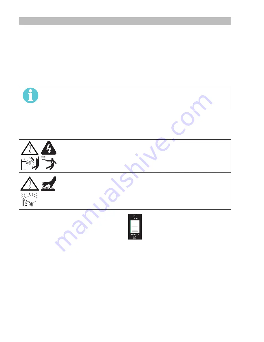
F.  Switch the LOCAL/REMOTE switch inside the  

wire feed compartment to LOCAL to use the 

Power Sources Amperage control or REMOTE 

for remote amperage using a Foot Control.

Summary of Contents for fabricator 211i

Page 1: ...A 12922 210 115V 208 230V 3163339 R vision AA Issue Date September 22 2015 Manual No 0 5450 Service Manual ESAB Fabricator 211i 3 IN 1 Multi Process Welding Systems esab com...

Page 2: ...take the time to read the entire manual especially the Safety Precautions They will help you to avoid potential hazards that may exist when working with this product YOU ARE IN GOOD COMPANY The Brand...

Page 3: ...ights reserved Reproduction of this work in whole or in part without written permission of the publisher is prohibited The publisher does not assume and hereby disclaims any liability to any party for...

Page 4: ...reof contained in this manual and accom panying labels and or inserts when installed operated maintained and repaired in accordance with the instructions provided This equipment must be checked period...

Page 5: ...dicators And Features 4 1 4 02 Attaching The TWECO Fusion 220A MIG Gun 4 7 4 03 Installing 33 44 lb Spool 12 diameter 4 8 4 04 Installing 12 5 lb Spool 8 diameter 4 9 4 05 Installing 1 lb Spool 4 diam...

Page 6: ...al 6 1 6 03 Front Panel Assembly Removal 6 2 6 04 Display PCB Removal 6 3 6 05 Back Panel Removal 6 4 6 06 Power Switch S1 and Power Cord Removal 6 5 6 07 Base Panel Removal 6 6 SECTION 7 ASSEMBLY PRO...

Page 7: ...arted up no one is unprotected when the arc is struck 3 The workplace must be suitable for the purpose be free from drafts 4 Personal safety equipment Always wear recommended personal safety equipment...

Page 8: ...lter lens and wear protective clothing Protect bystanders with suitable screens or curtains FIRE HAZARD Sparks spatter can cause fire Make sure therefore that there are no inflammable materials nearby...

Page 9: ...pliant to Standard CSA E60974 1 00 and UL 60974 1 The ESAB Fabricator 211i provides excellent welding perfor mance across a broad range of applications when used with the correct welding consumables a...

Page 10: ...ely qualified persons approved by ESAB Advice in this regard can be obtained by contacting an Accredited ESAB Distributor This equipment or any of its parts should not be altered from standard specifi...

Page 11: ...arc welding time out of every 10 minute period 20 of 10 minutes is 2 minutes During the other 8 minutes of the 10 minute period the Welding Power Source must idle and allowed to cool The thermal cut...

Page 12: ...A 23 3A 22 9A 24 5A 30 1A 29 4A Single Phase Generator Requirement 7 5 KW 3 7 KW MIG GMAW FCAW Welding Output 104 F 10 min 210A 20 24 5V 122A 60 20 1V 95A 100 18 8V 110A 45 19 5V 99A 60 19 0V 77A 100...

Page 13: ...ted so that the operator is forced to perform the work in a cramped kneeling sitting or lying position with physical contact with conductive parts 2 In locations which are fully or partially limited b...

Page 14: ...UCH live electrical parts SHUT DOWN welding power source disconnect input power employing lockout tagging procedures Lock out tagging procedures consist of padlocking line disconnect switch in open po...

Page 15: ...age 208 230V AC 115V AC Input Current at Maximum Output 32 Amps 30 Amps Maximum Recommended Fuse or Circuit Breaker Rating Time Delay Fuse UL class RK5 Refer to UL248 50 Amps 50 Amps 30 Amps 30 Amps M...

Page 16: ...and television transmitters and receivers 3 Computer and other control equipment 4 Safety critical equipment e g guarding of industrial equipment 5 The health of people around e g the use of pace mak...

Page 17: ...itance selected according to national regulations 6 Screening and Shielding Selective screening and shielding of other cables and equipment in the surrounding area may alleviate problems of interferen...

Page 18: ...ble substances or damage is present Have a qualified repair technician clean the regulator or repair any damage A 09845_AB Figure 3 6 Regulator to Cylinder Valve 6 Before opening the cylinder valve t...

Page 19: ...e down stream equipment hose hose fitting outlet fitting or low pressure gauge Check for leaks using an approved leak detector solution c If the high pressure gauge drops and the low pressure gauge in...

Page 20: ...nual 0 5450 3 12 Volt Ampere Curves Voltage Amperage Curves shows maximum voltage and amperage output capabilities of welding power source Curves of other set tings fall between curves shown Art A 112...

Page 21: ...1 Fabricator 211i Power Source Controls Indicators And Features 3 3A 4 5 6 7 9 8 10 11 12 13 14 2 1 16 15 21 A 12956 Figure 4 1 Front and Control Panel Figure 4 2 Rear Panel Connections Art A 10938 17...

Page 22: ...f approximately 10 seconds in all modes The amperage meter will hold the value until 1 any of the front panel controls are adjusted in which case the unit will revert to preview mode 2 welding is reco...

Page 23: ...r that the male plug is inserted and turned securely to achieve a sound electrical connection CAUTION Loose welding terminal connections can cause overheating and result in the male plug being fused i...

Page 24: ...ge Down Slope Arc Force The multifunction control knob is used to adjust Voltage MIG Mode Down slope LIFT TIG Mode and Arc Force STICK Mode depending on the welding mode selected NOTE The preview func...

Page 25: ...er with less weld spatter Higher arc control settings give a stronger driving arc which can increase weld penetration Soft means maximum inductance while Hard means minimum inductance 12 Trigger Mode...

Page 26: ...esigned for welding applications should be used 16 On Off Switch This Single Phase circuit breaker performs a dual function It is used to turn the unit on off and it will also trip in the event of a f...

Page 27: ...minutes after you stop welding After the 10 minutes has elapsed the fan will turn off In STICK mode the fan is on all the time The Fabricator 211i is designed with an intelligent fan control It autom...

Page 28: ...re to align the spool alignment pin on the hub with the mating hole in the wire spool 3 Replace the Wire Spool Hub Retaining Clip in the set of holes closest to the spool NOTE The Hub tension has been...

Page 29: ...alignment pin on the hub with the mating hole in the wire spool 3 Replace the Wire Spool Hub Retaining Clip in the set of holes closest to the spool NOTE The Hub tension has been pre adjusted at the f...

Page 30: ...ol rotates counter clockwise 3 Then place Flat Washer Large Hole Keyed Washer Spring Flat Washer Small Hole as shown in Figure 4 8 Finally secure with Wire Spool Hub Nut NOTE The Hub tension has been...

Page 31: ...ecure the pressue arm and wire drive tension knob and adjust the pressure accordingly refer to Section 4 07 Remove the contact tip from the MIG gun With the MIG gun lead reasonably straight feed the w...

Page 32: ...ensure that the Electricity Supply to the power source is switched off CAUTION The use of excessive pressure may cause rapid wear of the feed rolls shafts and bearing 4 08 Changing the Feed Roll To ch...

Page 33: ...tive welding terminal If in doubt consult the electrode wire manufacturer Welding current flows from the Power Source via heavy duty bayonet type terminals It is essential however that the male plug i...

Page 34: ...prevent falling or tipping CAUTION Loose welding terminal connections can cause overheating and result in the male plug being fused in the terminal Remove any packaging material prior to use Do not bl...

Page 35: ...sential however that the male plug is inserted and turned securely to achieve a sound electrical connection D Refer to the Weld Guide located on the inside of the wirefeed compartment door for further...

Page 36: ...wire feed compartment to SPOOL GUN Connect the shielding gas for the to the Shielding Gas Inlet on the rear panel of the Power Source 1 Make sure the welding power source is turned OFF before connect...

Page 37: ...r tipping CAUTION Loose welding terminal connections can cause overheating and result in the male plug being fused in the terminal Remove any packing material prior to use Do not block the air vents a...

Page 38: ...with an 8 pin plug must be used to turn the weld cur rent on off as well as providing remote control of the weld current E Fit the welding grade shielding gas regulator flowmeter to the shielding gas...

Page 39: ...urce via heavy duty bayonet type terminals It is essential however that the male plug is inserted and turned securely to achieve a sound electrical connection B Connect the work lead to the negative w...

Page 40: ...ESAB FABRICATOR 211i INSTALLATION SETUP 4 20 Manual 0 5450 Positive Welding Terminal Negative Welding Terminal Work Lead Electrode Holder Art A 11247 Figure 4 18 Setup for Manual Arc Welding...

Page 41: ...protection circuit to shut the unit down if the mains supply voltage is too high has operated A Check to see if mains supply voltage is 274VAC A generator with poor voltage regulation may cause a sup...

Page 42: ...way Incorrect TIG tungsten electrode Poorly prepared or worn TIG tungsten A B C D E F G H Use correct weld cable size Tighten welding connections Tighten work clamp Correct weld polarity Refer to weld...

Page 43: ...earthed and 1 The earth terminal of a fixed power source or 2 The earth terminal of the associated plug of a transportable power source Note that due to the dangers of stray output currents damaging f...

Page 44: ...re it falls within applicable ESAB power source specifications Table 5 3 Calibration Parameters Periodic calibration of other parameters such as timing functions are not required unless a specific fau...

Page 45: ...ect all components within these units Look in particular for the following a Loose or broken wires or connectors b Burned or scorched parts or wires or evidence of arcing c Any accumulation of metal d...

Page 46: ...r set to measure DC volts 5 07 Preliminary Check of the Control PCB WARNING Read and follow safety information in Section 5 03 before proceeding Art A 10751 IGBT Testing Multimeter Lead Placement Diod...

Page 47: ...imeter Lead Placement Ohms Resistor Positive meter lead to testpoint 8 Negative meter lead to testpoint 9 3 Table 5 7 Inrush PTC Multimeter set to measure ohms DIODE Testing Multimeter Lead Placement...

Page 48: ...5 9 Input Rectifier Multimeter set to measure Diode Voltage Measurements may be made directly onto the main input rectifier AC1 and AC2 may be measured from the pins on the mains supply plug with the...

Page 49: ...testpoint 3 385 VDC 10 Table 5 10 DC BUS Multimeter set to measure DC volts Note These DC voltages are at nominal mains supply voltage of 240VAC 110VAC 5 10 PCB Connectors 1 Power PCB Art A 10753 IN...

Page 50: ...VDC 5 Solenoid negative 0 VDC Table 5 15 DY1 Header pin function QF FJ Header Pin Pin function Signal 1 24V VRD positive 24 VDC 2 Solenoid negative 0 VDC 3 24V solenoid positive 24 VDC 4 0V 0 VDC Tab...

Page 51: ...al 1 Spool Gun Motor negative 0 VDC 2 Spool Gun Motor positive 24 VDC Table 5 22 SG M Header pin function connects to SGM header on display PCB PP Header Pin Pin function Signal 1 Spool Gun Switch 2 S...

Page 52: ...itch 2 Remote switch Table 5 28 REMOTE Header pin function connects to remote switch J12 Header Pin Pin function Signal 1 Serial display data eprom D IN 5 VDC digital 2 Serial display data LOAD 5 VDC...

Page 53: ...l 1 Motor negative 0 VDC 2 Motor positive 24 VDC Table 5 31 SGM Header pin function connects to SGM header on spoolgun PCB 15V Header Pin Pin function Signal 1 0VDC 0VDC 2 15VDC 15 VDC Table 5 32 15V...

Page 54: ...are wave 15 VDC pk 3 IGBT 2 pwm drive signal 15V p p square wave 15 VDC pk 4 IGBT 2 pwm drive signal 15V p p square wave 15 VDC pk 5 IGBT 1 pwm drive signal 15V p p square wave 15 VDC pk 6 Rectified s...

Page 55: ...OT2 Header pin function connects to NTCS header on Power PCB MB Header Pin Pin function Signal 1 Serial display data eprom D IN 5 VDC digital 2 Serial display data LOAD 5 VDC digital 3 Serial display...

Page 56: ...OTING 5 16 Manual 0 5450 5 11 DIP Switch Settings Control PCB 1 DIP Switch SW0 control PCB ON 1 2 Art A 12073 SW0 No SW0 Position 1 Set to OFF for Fabricator 211i 2 Set to OFF for Fabricator 211i Tabl...

Page 57: ...r to minimum Adjust Imin trimpot until output amps is 10A 0 2A Set front panel AMPS potentiometer to maximum Adjust Imax trimpot until output amps is 200A 1A Recheck settings Set front panel AMPS pote...

Page 58: ...ld read 30 Adjust W02 trimpot until motor volts are 4 2V 0 2V or motor feedroll shaft speed is 27rpm Set front panel WIRESPEED AMPS potentiometer to maximum AMPS display should read 218 Adjust W05 tri...

Page 59: ...ont View 8A 250V Fuse MIG GUN SPOOL GUN 1 1 K1 L1 L2 GND OT1 OT2 CR SOURCE QF DY WVIN JC 1 2 MB 1 POT1 1 CR JC QF DY GND 24VDC 3 POT MAX 5VDC 2 WIPER 1 POT MIN RED BLK YEL 1 24VDC 1 1 OUTPUT 3 OUTPUT...

Page 60: ...nction of the capacitors C20 and C21 the voltage at this point is approximately half the DC bus voltage Secondary output voltage from the transformer is rectified by the output diodes T13 T14 T15 T16...

Page 61: ...sconnect DRIVE harness from DRIVE connector 3 Disconnect SOURCE harness from SOURCE connector 4 Disconnect CR harness from CR connector 5 Disconnect FUNs harness from FUNs connector 6 Disconnect IGBT...

Page 62: ...sembly Removal WARNING Read and follow safety information in Section 5 03 before proceeding with disassembly 1 Screws on front panel 2 Positive output terminal bolts Unscrew output terminal bolts 3 Ne...

Page 63: ...SSEMBLY PROCEDURES 6 04 Display PCB Removal WARNING Read and follow safety information in Section 5 03 before proceeding with disassembly 1 Remove Control Panel screw 4 2 Display PCB 3 Disconnect the...

Page 64: ...and follow safety information in Section 5 03 before proceeding with disassembly 1 Remove the screws on the back 2 Remove Rear Panel screws 3 Remove The Ground Wire 4 Wire from Power PCB Disconnect th...

Page 65: ...ound Wire 3 Remove the screws which control the supply cord 4 Remove the two screws and push SW1 out from the rear panel 5 Remove the two supply wires from the switch 6 Remove the supply wires which c...

Page 66: ...07 Base Panel Removal WARNING Read and follow safety information in Section 5 03 before proceeding with disassembly 1 Remove Wire Feeder Screws 2 Remove inductor assembly Screws 3 Remove Power PCB as...

Page 67: ...BLY PROCEDURES 7 01 Installing Base Panel 1 Power PCB assembly 2 Install Power PCB assembly screws 3 Install inductor assembly Screws 4 Install Wire Feeder Screws 5 Install Center Panel Screws 1 4 3 2...

Page 68: ...stall fan 4 Reconnect the pipe to gas inlet and the screw 5 Reconnect the supply wires 6 Reconnect the supply wires which connect to power PCB 7 Install the two screws 8 Reinstall magnetic core onto G...

Page 69: ...ve output terminal bolts and tighten with 17mm wrench Note reconnect wires pay attention to the wire colour Reconnect negative output terminal bolts and tighten with 17mm wrench note reconnect wires a...

Page 70: ...arness into m IGBT OT2 connector 7 Plug harness into IGBT OT1 connector 8 Plug harness into GUN connector 9 Plug harness into QF DY connector 10 Plug harness into WVIN connector 11 Plug harness into M...

Page 71: ...EDURES 7 05 Installing Cover Panel and Door Panel 1 Install Ground Screw which connects the ground wire to the cover 2 Install cover panel and door panel Install Screws Tighten screws Art A 11363_AC 1...

Page 72: ...ESAB FABRICATOR 211i ASSEMBLY PROCEDURES 7 6 Manual 0 5450 This Page Intentionally Blank...

Page 73: ...MIG Gun TWECO WELDSKILL 220A MIG GUN PARTS ITEM PART NO DESCRIPTION 1 1210 1112 Nozzle 1 2 12 7 mm Flush 2 1110 1102 Contact Tip 035 0 9mm 3 1510 1140 Gas Diffuser 4 2042 2053 Microswitch 5 2042 2054...

Page 74: ...62F VNS 37 VNS 37F VNS 75FAS 2 Velocity Contact Tip VTS 23 VTS 30 VTS 35 VTS 40 VTS 45 VTSA 364 VTS 52 VTS 116 VTSA 116 VTS 564 3 Handle Trigger Repair Kit F80 4 Conduit Assembly WS42 3035 15 5 5A Tw...

Page 75: ...ESAB FABRICATOR 211i Manual 0 5450 8 3 KEY SPARE PARTS 8 03 Power Source Spare Parts Art A 11250 1 2 3 6 7 9 8 10 11 12 14 13 15 16 18 19 4 5 20 22 23 24 25 26 17 30 31 29 32 33 34 36 35 Figure 8 3...

Page 76: ...r Friction Spool Hub 19 W7005609 Spool Hub 20 W7004966 Adapter ESAB 4 141i 211i 21 W7005619 Guide Inlet 023 045 not shown 22 W7004967 Guide Outlet 023 045 23 W7005557 Front Panel Fab 211i UL CSA 24 W7...

Page 77: ...oll 030 035 0 8 0 9 mm U groove Part No 7977731 Drive Roll 040 3 64 1 0 1 2 mm U groove Part No 7977264 Drive Roll 030 035 0 8 0 9 mm V knurled Part No 7977732 Drive Roll 045 1 2 mm V knurled Part No...

Page 78: ...ESAB FABRICATOR 211i OPTIONS ACCESSORIES 9 2 Manual 0 5450 This Page Intentionally Blank...

Page 79: ......

Page 80: ...50 92 22 ESAB international AB Gothenburg Tel 46 31 50 90 00 Fax 46 31 50 93 60 SWITZERLAND ESAB AG Dietikon Tel 41 1 741 25 25 Fax 41 1 740 30 55 UKRAINE ESAB Ukraine LLC Kiev Tel 38 044 501 23 24 F...

Reviews: