background image

Page 17

Notice G05 - 3 590 503
Issue: 11/2011 - Rev.A

ERVOR (SCA) - 6, Rue Désiré Granet - Z.I. du Val d'Argent - 95100 ARGENTEUIL FRANCE

 (33) 01 34 11 50 00 

 (33) 01 34 11 50 10

Web : www.ervor.com - Email : [email protected]

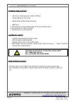
8 - C - FIRST START- UP

8 - C - 1  REMOVAL FROM STORAGE

)

)

)

)

)

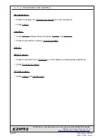
Drain the storage oil from the compressor carefully.

)

Fill the compressor with the recommended oil.
(see chapter "general characteristics of recommended oil").

)

Start the compressor and run for 15min off load, increase pressure to maximum
service pressure for 15 minutes.
Wait for 30 minutes before draining the oil.

)

Fill the compressor with the recommended oil .

)

For oil level and draining see chapter "lubrication of compressors".

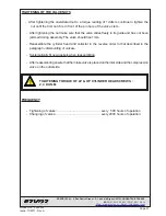
8 - C - 2  COUPLING MOUNTING

This coupling has been specially designed to absorb vibrations and variations between the
compressor and its drive motor. It can be used with an electric motor drive as well as a
combustion engine.

- COUPLING TYPE ...................................................... AC2
- NUMBER OF BLADES .............................................. 24
- MAXIMUM POWER TRANSMITTED ......................... 8 CV - 5,8KW

Ervor Type 

AC2 

couplings


allow a maximum linear misalignment of up to 0°30' between the

compressor and the drive motor in all directions.

Recommendations for assembly :

)

)

)

)

)

Fit the short plate boss on the end of the compressor drive shaft

)

)

)

)

)

Fit the short plate boss on the end of the motor drive shaft

)

)

)

)

)

Mount the drive motor onto the common frame

)

)

)

)

)

Straighten block

)

)

)

)

)

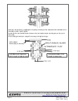
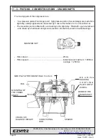
Fit the intermediate plate onto the plate on the drive motor side by mounting the
semi-elastic blades as shown on the following page .

Summary of Contents for G05

Page 1: ... 503 Issue 11 2011 Rev A ERVOR SCA 6 Rue Désiré Granet Z I du Val d Argent 95100 ARGENTEUIL FRANCE 33 01 34 11 50 00 33 01 34 11 50 10 Web www ervor com Email info ervor com AIR COMPRESSOR OPERATING AND MAINTENANCE MANUAL G05 ...
Page 2: ...d by contract and Ervor reserves the right to alter its compressors accessories and corresponding documentation without notice No part of this manual may be reproduced without the written permission of Ervor Compressors Model G05 Serial number Ervor reference 8 101 010 Standard 8 101 031 Bureau Véritas without oil level switch 8 101 073 Bureau Véritas with oil level switch 8 101 034 Lloyd s Regist...

Page 3: ...5 DANGER ZONES 11 6 STORAGE 13 6 A UNDER 3 MONTHS 13 6 B 1 YEAR MAXIMUM 13 6 C ABOVE 1 YEAR 13 6 D STORAGE OIL 14 7 INSTALLATION 15 8 USING THE COMPRESSOR FOR THE FIRST TIME 16 8 A SAFETY REMINDER 16 8 B SAFETY MEASURES 16 8 C FIRST START UP 17 8 C 1 REMOVAL FROM STORAGE 17 8 C 2 COUPLING MOUNTING 17 8 C 3 DIRECTION OF ROTATION 20 8 C 4 PROCEDURE FOR STARTING 22 9 SAFETY INSTRUCTIONS 23 9 A USED O...

Page 4: ...R HEADS VALVES 28 11 B 1 COMPOSITION OF VALVES ON CYLINDER HEADS 28 11 B 2 MAINTENANCE OF VALVES 30 11 C PISTONS CONNECTING RODS CRANKSHAFTS 32 11 D CYLINDERS PISTONS 34 11 D 1 CYLINDERS 34 11 D 2 PISTONS 34 11 E PISTON RINGS 34 11 E 1 MOUNTING OF RINGS 35 12 FAILURE ANALYSIS 38 12 A START UP FAILURE 38 12 A 1 THE COMPRESSOR DOES NOT START 38 12 B RUNNING FAILURE 38 12 B 1 THE COMPRESSOR STARTS BU...

Page 5: ...mum Noise level at 1 metre 80 dB A Number of cylinders 2 flat twin Number of stages 2 Low pressure cylinder bore 125 mm High pressure cylinder bore 50 mm Piston stroke 25 mm Cooling coil copper coil between stages Absorbed power 3 68 kW Maximum ambient temperature 40 C max Minimum ambient temperature 10 C 2 horizontal air cooled cylinders Multi Stage Revolution Speed Maximum 1500 rpm Minimum 600 r...

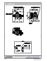
Page 6: ...ge 6 Notice G05 3 590 503 Issue 11 2011 Rev A ERVOR SCA 6 Rue Désiré Granet Z I du Val d Argent 95100 ARGENTEUIL FRANCE 33 01 34 11 50 00 33 01 34 11 50 10 Web www ervor com Email info ervor com 2 LAYOUT ...

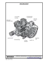
Page 7: ...t 95100 ARGENTEUIL FRANCE 33 01 34 11 50 00 33 01 34 11 50 10 Web www ervor com Email info ervor com EXPLODED DIAGRAM bronze bushed connecting rod double bearing Protective grill copper coil eccentric camshaft differential monobloc piston semi flexible coupling light alloy impeller special valves ...

Page 8: ...nddefectivematerial providedthatthe user complies with the instructions given in this manual The Ervor guarantee only covers the free replacement of parts that have been proved defective by our Technical Department The guarantee does not cover breakdowns due to lack of maintenance or the non compliance of instructions given for correct running of the compressor It is up to the user to guarantee hi...

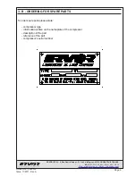
Page 9: ...00 ARGENTEUIL FRANCE 33 01 34 11 50 00 33 01 34 11 50 10 Web www ervor com Email info ervor com 3 B ORDERING FOR SPARE PARTS To order spare parts please state compressor type information written on the nameplate of the compressor description of the part reference of the part compressor s serial number ...

Page 10: ...Granet Z I du Val d Argent 95100 ARGENTEUIL FRANCE 33 01 34 11 50 00 33 01 34 11 50 10 Web www ervor com Email info ervor com 4 DESCRIPTION OF DANGER SIGNALS HOT PARTS HIGH PRESSURE MOVING PARTS NOISE ROTATING FAN FLUID EJECTION DANGEROUS ELECTRIC VOLTAGE NON BREATHABLE AIR ...

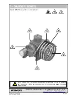
Page 11: ...d Argent 95100 ARGENTEUIL FRANCE 33 01 34 11 50 00 33 01 34 11 50 10 Web www ervor com Email info ervor com 5 DANGER ZONES ANY WORK ON THE ELECTRICAL INSTALLATION EVEN OF MINOR IMPORTANCE MUST BE CARRIED OUT BY PROFESSIONALLY SKILLED PERSONNEL Beware of the following risks on our compressor ...

Page 12: ...e 12 Notice G05 3 590 503 Issue 11 2011 Rev A ERVOR SCA 6 Rue Désiré Granet Z I du Val d Argent 95100 ARGENTEUIL FRANCE 33 01 34 11 50 00 33 01 34 11 50 10 Web www ervor com Email info ervor com Blank page ...

Page 13: ...nder heads and valves carefully Inject storage oil into the cylinder heads and valves Mount the cylinder heads Fill the compressor with storage oil Start the compressor and run for 10 min off load introduce 20cl of oil into the compressor air intake A sealed package long term category 4C with dehydrating packs conforming to S E I norms 6 C ABOVE 1 YEAR Every year Drain storage oil carefully Fill u...

Page 14: ...Val d Argent 95100 ARGENTEUIL FRANCE 33 01 34 11 50 00 33 01 34 11 50 10 Web www ervor com Email info ervor com 6 D STORAGE OIL Storage oil Can oil 25L ref 7 550 035 type ANTICORIT VCI UNI 0 40 Technical data Density at 25 C 0 9 0 97 g ml Flash point min 55 C Viscosity at 20 C 250 mm2 s ...

Page 15: ...on and sheltered from cold The compressor must be placed at minimum distance of 400 mm from any wall or any other machine for efficient cooling of the compressor Install the compressor on a mounting plate or on a solid floor with shock absorbers IF THE TECHNICAL ROOM IS TOO SMALL FORCED VENTILATION SHOULD BE INSTALLED FOR EFFICIENT COOLING THE TEMPERATURE OF THE TECHNICAL ROOM SHOULD NOT EXCEED 40...

Page 16: ...USING THE COMPRESSOR FOR THE FIRST TIME 8 A SAFETY REMINDER DO NOT START THE COMPRESSOR WHEN PEOPLE ARE WORKING ON IT ONLY A SKILLED TECHNICIAN WHO HAS READ THIS MANUAL SHOULD OPERATE AND OR MAKE ADJUSTMENTS TO THE COMPRESSOR NEVER START THE COMPRESSOR WITHOUT THE COUPLING PROTECTION NEVER CLOG THE AIR FILTER 8 B SAFETY MEASURES BEFORE THE FIRST START UP CHECK THE OIL LEVEL CHECK THE SUPPLY VOLTAG...

Page 17: ...g see chapter lubrication of compressors 8 C 2 COUPLING MOUNTING This coupling has been specially designed to absorb vibrations and variations between the compressor and its drive motor It can be used with an electric motor drive as well as a combustion engine COUPLING TYPE AC2 NUMBER OF BLADES 24 MAXIMUM POWER TRANSMITTED 8 CV 5 8KW Ervor Type AC2 couplings allow a maximum linear misalignment of ...

Page 18: ...upling according to the measurements indicated in the illustration below lightly tighten Assemble the semi elastic blades between the intermediate plate and the plate on the motor drive side Check setting dimensions adjust if necessary and tighten fixings RULE 2mm 0 3 0 2mm MAXI Horizontally vertically 0 30 maxi 0 30 maxi COMPRESSOR READING WITH PLATE SHORT HUB INTERMEDIATE PLATE SEMI FLEXIBLES BL...

Page 19: ...LASTIC BLADES It is absolutely necessary that after mounting both plates should move angularly in relation to each other The measurement between these two plates must be maintained while mounting Under no circumstances must the two plates be bonded together BREAKING OF SEMI FLEXIBLE BLADES This is systematically due to a fault in the alignment between the drive motor and compressor or to a fault i...

Page 20: ...iller pipe Inform us of any non standard mountings DRIVING BY AN ELECTRIC MOTOR THREE PHASE SUPPLY When the power supply of the motor is connected check the direction of rotation The direction of rotation of an electric motor can be inverted by reversing two of the supply wires to the terminal box of electric motor DRIVING BY A COMBUSTION ENGINE GASOLINE OR DIESEL The combustion engines used for d...

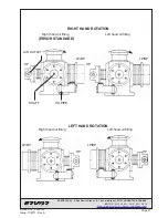
Page 21: ...100 ARGENTEUIL FRANCE 33 01 34 11 50 00 33 01 34 11 50 10 Web www ervor com Email info ervor com LEFT HAND ROTATION OIL PIPE SHAFT AIR OUTLET RIGHT HAND ROTATION LP BP LP BP HP Right hand oil filling ERVOR STANDARD Left hand oil filling HP Left hand oil filling Right hand oil filling HP HP LP BP LP BP ...

Page 22: ...R STARTING Air compressor Check the storage oil is drained and replaced by recommanded oil Check oil level Coupling Check distance between these two plates blocking and alinement Check the protection coupling is correctly installed Driving Electric motor Check the electrical motor protection by circuit breaker with appropriate adjustment Check the sense of rotation Thermic engine Check oil level a...

Page 23: ...FETY INSTRUCTIONS Stop the compressor Cut off the general supply and circuit breaker Make sure power supply is disconnected Isolate the compressor from the air network by closing the pressure delivery isolating valve Air the compressor Wait A few minutes for the compressor s internal pressure to shut down to 0 bar 9 A USED OIL DISPOSAL WASTE OIL DISPOSAL MUST BE IN ACCORDANCE WITH COUNTRY LEGISLAT...

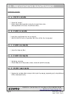
Page 24: ... using the manual drain valve Not applicable in the case of automatic drain 10 B EVERY 50 HOURS Drain the condensates from the air receiver After the first 50 hours of operation drain the oil from the compressor 10 C EVERY 200 HOURS Clean the intake air filter 10 D EVERY 500 HOURS Discharge oil casing Check intake and compression valves clean and grind if necessary 10 E EVERY 1000 HOURS Replace th...

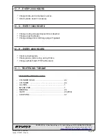
Page 25: ... valves Grind cylinder head if necessary 10 G EVERY 3000 HOURS Change cooling coil assembly and shock absorber Change coupling blades Change oil plug and oil discharge plug with gaskets 10 H EVERY 4000 HOURS Check connecting rods Check pistons pistons ring and cylinders Change cylinder head LP HP with valves 10 I TIGHTENING TORQUE TIGHTENINGTORQUEindaN m CYLINDER HEAD 2 4 CYLINDER 2 4 OIL PIPE 1 I...

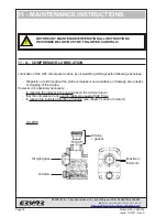
Page 26: ...ESSOR LUBRICATION Lubrication of the G05 compressor is done by oil splashing which givesthe following advantage Dispersion of oil throughout the entire compressor and avoidance of damage due to leaks or clogging of the oil pipe However it is absolutely necessary to maintain the oil level in the casing above the minimum level that the compressor runs over its minimum speed of 600 T min to respect t...

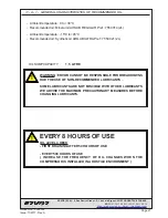
Page 27: ...4 2L Ambient temperature 15 C to 45 C Recommended oil Synthetic oil AIRLUB ULTRAP ref 7 550 021 2L OILSUMPCAPACITY 1 5 LITRE WARNING ERVOR CANNOT BE RESPONSIBLE FOR BREAKDOWNS DUE THE USE OF NON RECOMMENDED LUBRICANTS SOME LUBRICANTS ARE NOT MISCIBLE WITH OTHER LUBRICANTS WE ADVISE THE MAXIMUM PRECAUTIONARY MEASURES BEFORE CHANGING LUBRICANTS EVERY 8 HOURS OF USE OIL LEVEL CHECK FIRST DRAINING AFT...

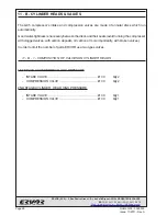
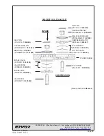
Page 28: ...which run automatically Good water tightness is necessary between the discs and their seats avoid running the compressor with clogged valves with carbon deposits oil carbon or more importantly with broken valves In order to limit the number of parts ERVOR use two types valves 11 B 1 COMPOSITION OF VALVES ON CYLINDER HEADS 1ST STAGE CYLINDER HEAD LOW PRESSURE INTAKE VALVE Ø 30 Qty 2 COMPRESSION VAL...

Page 29: ...P30CPQ7 3 933 003 SPLIT PIN PCV2X16 7 436 004 CASTELLATED NUT PCAX8bisQ13 3 933 024 BELLEVILLE WASHER PCRBLM8x18 7 421 009 COMPRESSIONSTOP PB30AQ2 3 936 007 VALVE SPRING P30RSQ5 3 933 012 VALVE STEM PCAX8Q11 3 925 002 SPLIT PIN PCV2X16 7 436 004 BELLEVILLE WASHER PCRBLM8x18 7 421 009 CASTELLATED NUT PCAX8bisQ13 3 933 024 VALVE SPRING P30RSQ5 3 933 012 VALVE STEM PCAX8Q11 3 925 002 INTAKE STOP PB30...

Page 30: ... valve and the seat b that bearings are in good condition c that there are no broken springs LAPPING OF VALVES Cylinder head bearings are steel on steel Use fine quality oil grinding paste Normally lap the valve on the cylinder head After lapping clean the whole set cylinder head valve with a good solvent dry the set properly with compressed air BE CAREFUL NEVER TO CLEAN THE VALVES WITH INFLAMMABL...

Page 31: ...r tightening the nut make sure that the valve slides freely in its guide and has not been jammed during assembly The valve should rise 1mm Reassemble the cylinder head and collector in the reverse order to that described in the paragraph dismounting of valves Systematically fit new gaskets when reassembling After reassembling ensure that the intake valve is placed on the inlet side and the compres...

Page 32: ... OF THE CRANK SHAFT CRANK SHAFT WITH BALANCE WEIGHT 11 C PISTONS CONNECTING RODS CRANKSHAFTS The moving parts of the compressor are 1 low pressure piston First stage and 1 high pressure piston Second stage are made from light alloy axially opposed and connected by 4 cast arms made to form a monobloc set The monobloc piston is fitted with a connecting rod in light alloy fitted with a gun metal bush...

Page 33: ...oc piston with the connecting rod can be removed after removal of the cylinders REMOUNTING OF THE CRANKSHAFT Position the piston with the connecting rod in the casing Mount the crankshaft in the bearing Fit the assembly in the casing with the crankshaft in the correct orientation Place the spacer on the side towards the circlips Fit the bearing housing Remount the air fan and the coupling plate or...

Page 34: ...eated alloy Machined dimensions LOW PRESSURE 1ST STAGE 124 7mm 0 0 05 HIGH PRESSURE 2ND STAGE 49 8mm 0 0 05 11 E PISTON RINGS Cast steel adjusted right cut Manufacturers dimensions LOW PRESSURE 1ST STAGE ANTI LEAK 125mm x 4 Qty 2 SCRAPER 125mm x 5 Qty 2 HIGH PRESSURE 2ND STAGE ANTI LEAK 50mm x 3 Qty 3 SCRAPER 50mm x 3 Qty 1 Piston ring diameter play at cut ANTI LEAK L P 125mm 0 40 to 0 55 mm SCRAP...

Page 35: ...n rings with holes for the return flow of oil to the casing are fitted in the grooves see figure below MOUNTING OF SCRAPER PISTON RINGS There is no special direction for mounting MOUNTING OF ANTI LEAK PISTON RINGS Anti leak piston rings used in ERVOR compressors are conical Therefore it is imperative to mount them in the correct direction A mark is etched on one of the faces of the anti leak pisto...

Page 36: ...st work perpendicular to the cylinder axis and therefore the side play between the piston ring and its groove should not be too large If the wear rate is reached prepare to change the pistons and piston rings CIRCUMFERENTIALWEARINGOFPISTONRINGS Removepiston rings Manually place each piston ring perpendicular to the cylinder axis Play at cut must not exceed the play indicated below Piston ring diam...

Page 37: ...nt 95100 ARGENTEUIL FRANCE 33 01 34 11 50 00 33 01 34 11 50 10 Web www ervor com Email info ervor com 0 05mm maxi 0 01mm to 0 02mm PISTON RING WEARING READING MOUNTING PLAY PISTON RING 2nd STAGE CRANK CASE CYLINDER CYLINDER 1st STAGE 1st STEP 2nd STEP MOUNTING OF PISTON IN CYLINDER PISTON MOUNTED ...

Page 38: ...RANCE 33 01 34 11 50 00 33 01 34 11 50 10 Web www ervor com Email info ervor com 12 FAILURE ANALYSIS 12 A START UP FAILURE 12 A 1 THE COMPRESSOR DOES NOT START 12 B RUNNING FAILURE 12 B 1 THE COMPRESSOR STARTS BUT TRIPS 12 B 2 THE COMPRESSOR RUNS BUT THERE IS NO DELIVERY PRESSURE 12 B 3 THE COMPRESSOR HEATS ABNORMALLY ...

Page 39: ...V C V V V C Set of piston rings LP HP 8 970 089 V C V Cooling coil assembly G05 8 141 541 C C Standard Bureau Veritas Cooling coil assembly G05 Lloyd s 8 141 547 C C Cooling coil shock absorber set G05 8 960 007 C C Set of AC2 coupling blades 8 970 054 U V C V C Oil plug gasket 7 603 007 U V C V C Oil discharge plug 7 603 017 U V C V C Oil discharge plug gasket 7 503 002 U V C V C Intake filter mo...

Page 40: ...40 Notice G05 3 590 503 Issue 11 2011 Rev A ERVOR SCA 6 Rue Désiré Granet Z I du Val d Argent 95100 ARGENTEUIL FRANCE 33 01 34 11 50 00 33 01 34 11 50 10 Web www ervor com Email info ervor com 14 PARTS LIST ...

Page 41: ...G05PAT18 1 934 007 15 INTAKE FILTER 1 PCG04FIQ1019 7 200 001 16 OIL DISCHARGE PLUG 1 PCBMD001300 7 603 017 17 OIL PLUG 1 PCTPS20 7 603 007 18 OIL PIPE ASSEMBLY 1 P PIPEHUILE 8 934 000 L P CYLINDER 1st STAGE Standard 1 PG055D4 3 931 003 L P CYLINDER 1st STAGE Bureau Veritas 1 3 931 004 L P CYLINDER 1st STAGE Lloyd s Register 1 3 931 021 20 BEARING 1 PG056T29 3 936 011 20A CIRCLIPS 1 PC72I 7 430 008...

Page 42: ... weight Cast iron Ft15c Bearing Cast iron Ft25c Pistons Aluminium AU4NT Piston spindle Steel 16NC6 carburized ground Rings Grey pig iron with phosphate coat Cylinders Cast iron Ft25c Cylinder heads Steel XC38 Valves Special steel Intake pipe Aluminium alloy AU12 Copper coil between stages Annealed red copper tube X 610 Fan Aluminium alloy AU12 Protective grill Steel E24 Snifting valve Aluminium al...

Reviews: