background image

 DESCRIPTION OF THE PRODUCT

Descripcion_10 v1.2.fm 

- 10/12/07

VULCAN hydraulic actuator

53

 4 

GENERAL CHARACTERISTICS OF THE ACTUATOR

Characteristics common to all models

Characteristics specific to each model

Model

General

Models -M

Power supply (V/Hz)

230/50

110/60

Intensity (A)

1

2

Power consumed (W)

230

220

Condenser (μF)

10

20

Protection factor (IP)

54

Maximum force (N)

7.000

Spindle speed (mm/s)

10 (20 fast models -R-)

Service temperature (ºC)

-10/+90 (-30/+90 models -F-)

Work cycle (%)

100

Weight (Kg).

9.5 (short models); 11 (long models)

Use

Collective

Model

Absorption

S: safety system
A: absorption 
2A: dual absorption

Travel 
spindle 
(mm)

3: short
4: length

Lock

1: reversible
3: dual lock
5: opening lock

a

6: closing lock 

b

a.

Opening lock: locks the introduction of the spindle

b.

Closing lock: locks the extension of the spindle

Particularities

R: fast
F: cold
C: hydraulic lock outlet
M: 110V, 60Hz

VU31

No

265 Reversible

VUA31

Upon close

265 

Reversible

VU2A31

Upon close and opening

265 

Reversible

VUA31C

Upon close

265 

Reversible

Hydraulic lock outlet

VU2A31C Upon close and opening

265 

Reversible

Hydraulic lock outlet

VUA41

Upon close

400 

Reversible

VU2A41

Upon close and opening

400 

Reversible

VUA41C

Upon close

400 

Reversible

Hydraulic lock outlet

VU2A41C Upon close and opening

265 

Reversible

Hydraulic lock outlet

VUS31

Safety system 
patented by ERREKA

265 Reversible

VUS41

Safety System 
patented by ERREKA

400 Reversible

VUA33

Upon close

265 

Dual lock

VUA43

Upon close

400 

Dual lock

VUA35

Upon close

265 

Opening lock

VUA45

Upon close

400 

Opening lock

VUA36

Upon close

265 

Closing lock

VUA46

Upon close

400 

Closing lock

Summary of Contents for VU2A31

Page 1: ...TIENTES MANUAL DEL INSTALADOR ACTIONNEUR HYDRAULIQUE POUR PORTES BATTANTES MANUEL DE L INSTALLATEUR HYDRAULIC ACTUATOR FOR HINGED DOORS INSTALLER S MANUAL ACCIONADOR HIDRÁULICO PARA PORTAS BATENTE MANUAL DO INSTALADOR www erreka com VULCAN ...

Page 2: ...tuator _________________________ 53 Manual operation __________________________________________ 55 Declaration of conformity ____________________________________ 55 Unpacking and content 56 Unpacking_________________________________________________ 56 Content___________________________________________________ 56 Installation 57 Necessary tools_____________________________________________ 57 Initia...

Page 3: ...ld lead to accidents or failures 4 INSTALLER S QUALIFICATIONS n The installation should be completed by a professional installer complying with the following requirements He she must be capable of carrying out mechanical assemblies in doors and gates choosing and implementing attachment systems in line with the assembly surface metal wood brick etc and the weight and effort of the mechanism He she...

Page 4: ...d 10 INSTALLATION COMPONENTS 1 Actuator 2 Flashing lamp 3 Door 4 Exterior photocells 5 Key selector 6 Wall button 7 Control panel 8 Connections box 9 Electrical installation 10 Interior photocells 11 Electrolock obligatory in reversible models 12 Closing stopper 13 Reception antenna ELECTRICAL CABLING Element Nº threads x section Maximum length A General power supply 3x1 5mm2 30m B Flashing lamp 2...

Page 5: ...ntle halt The VU2A models have absorption for the two travels opening and closing VUS Models with patented safety system The VUS models are fitted with an exclusive safety system patented by ERREKA This safety system is capable of detecting the collision of the door against an obstacle informing the control panel of this incident in order to invert operation Hence the VUS models along with the ERR...

Page 6: ...ning lock locks the introduction of the spindle b Closing lock locks the extension of the spindle Particularities R fast F cold C hydraulic lock outlet M 110V 60Hz VU31 No 265 Reversible VUA31 Upon close 265 Reversible VU2A31 Upon close and opening 265 Reversible VUA31C Upon close 265 Reversible Hydraulic lock outlet VU2A31C Upon close and opening 265 Reversible Hydraulic lock outlet VUA41 Upon cl...

Page 7: ...eaf and the presence of wind may bring notable differences in the values of the chart An electrolock must be used in the reversible models Values for orientation purposes The form of the leaf and the presence of wind may bring notable differences in the values of the chart We recommend using an electrolock for leaf lengths of over 2 5m Limits on use of the locked models Models with 265mm spindle M...

Page 8: ...the standards EN 13241 1 and EN 12453 The VULCAN electromechanical actuator complies with safety legislation in line with the following directives and standards 73 23 EEC and successive modification 93 68 EEC 89 366 EEC and successive modifications 92 31 EEC and 93 68 EEC UNE EN 60335 1 Unlock for manual operation 1 Lift the top and introduce the key 1 in the unlocking screw 2 2 Rotate the unlocki...

Page 9: ...ed that a piece is missing or deteriorated contact the closest technical service 2 CONTENT Fig 3 VULCAN Actuator Content 1 Fork axles caps 2 Safety washers 3 Fork vertical pin ø 12mm L 37mm 4 Fork 5 Fork horizontal pin ø 10mm L 57 2mm 6 Gland top screws 7 Gland top 8 Glands 9 Gland nut 10 Hydraulic motor equipment model with lock 11 Spindle cover 12 Spindle cover top 13 Spindle cover tops 14 Spind...

Page 10: ...oor must have a closing stopper and an opening stopper The door must be easy to manipulate manually namely This must be balanced in order to ensure the effort made by the motor is minimum There should be no stiffness throughout its travel n Do not install the actuator in a door which does not work correctly in manual operation as this may lead to accidents Repair the door before installing Environ...

Page 11: ... axis O IT IS VERY IMPORTANT TO RESPECT THE DIMENSIONS If the dimensions are not respected exactly the spindle will not make the whole travel meaning the absorption system will not work The dimensions are selected using either the table or the attached chart The table indicates some specific cases whilst the chart shows all the possible cases The assembly dimensions depend on the opening angle of ...

Page 12: ...0 110º 105 120 i Use of the chart For a specific opening angle multiple A B pairs can be chosen Generally one of them will be determined by the characteristics of the installation size of the pillar presence of walls etc 1 Select the specified dimension in the chart 2 Following the grid move from the dimension to the line corresponding to the required opening angle 3 Following the grid move to the...

Page 13: ...110º 95 125 i Use of the chart For a specific opening angle multiple A B pairs can be chosen Generally one of them will be determined by the characteristics of the installation size of the pillar presence of walls etc 1 Select the specified dimension in the chart 2 Following the grid move from the dimension to the line corresponding to the required opening angle 3 Following the grid move to the ot...

Page 14: ...0 110º 190 155 i Use of the chart For a specific opening angle multiple A B pairs can be chosen Generally one of them will be determined by the characteristics of the installation size of the pillar presence of walls etc 1 Select the specified dimension in the chart 2 Following the grid move from the dimension to the line corresponding to the required opening angle 3 Following the grid move to the...

Page 15: ...10º 140 195 i Use of the chart For a specific opening angle multiple A B pairs can be chosen Generally one of them will be determined by the characteristics of the installation size of the pillar presence of walls etc 1 Select the specified dimension in the chart 2 Following the grid move from the dimension to the line corresponding to the required opening angle 3 Following the grid move to the ot...

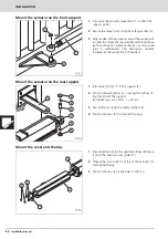
Page 16: ... VERY IMPORTANT TO RESPECT THE DIMENSIONS If the dimensions are not respected the spindle will not make the whole travel meaning the absorption system will not work 2 Weld the reinforcements 3 and 4 to the supports 1 and 2 O Carry out the welding with the actuator withdrawn and at a distance If not the spindle may become damaged from welding splatter which could lead to failures and oil leaks 1 In...

Page 17: ...tion distance The absorption distance reduces as the swivel joint is unthreaded The absorption distance increases as the swivel joint is threaded 1 Introduce the fork 1 in the support 2 2 Position the vertical pin 3 crossing the orifices of the fork and of the support Vertical pin ø 12mm L 37mm 3 Secure the pin using the safety washers 4 4 Position the caps 5 to close the housing 1 Introduce the r...

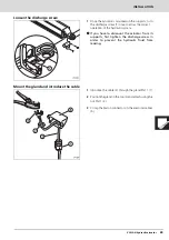
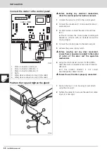
Page 18: ...he discharge screw 1 once to allow the correct operation of the hydraulic system O If you have to dismount the actuator from its supports first tighten the discharge screw in order to prevent the hydraulic fluid from leaking 1 Introduce the cable 3 through the gland PG11 1 2 Position the gland in the top 4 and attach using the nut PG11 2 3 Crimp the Faston connectors in the electrical cables 5 ...

Page 19: ...lectrical grid 5 Activate the power supply switch n Before carrying out any door movement ensure there is no person or object in the radius of action of the door and the operation mechanisms 6 Using the control panel controls CLOSE OPEN check the motor connections are correct rotation direction If the rotation direction is not correct interchange the cables 2 and 3 n Ensure the earth cable is prop...

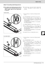
Page 20: ...eration 3 OPENING PRESSURE white colour cap screw 3 The Opening Pressure is more exactly the pressure during the retraction of the spindle In inward opening installations it corresponds to the opening operation In outward opening installations it corresponds to the closing operation 4 Replace the caps 1 respecting the colours 1 Remove the cap 1 which covers the adjustment screws 2 CLOSING PRESSURE...

Page 21: ...e values indicated in standard EN 12453 2000 as shown in the attached chart The measurements must be made in line with the method described in standard EN 12445 2000 For models without a patented safety device the door should not exercise a force in excess of 150N 15kg 3 Check the operation of all the installation elements especially the protection systems and the manual operation unlocking system...

Page 22: ...Check the state of the condenser By activating the opening or closing controls the actuator is enabled but the door does not move The assembly dimensions of the supports have not been respected Dismount the supports and then put them back in place respecting the assembly dimensions The screw for manual operation is in unlock position Using the corresponding wrench position the screw in automatic o...

Page 23: ...TENANCE AND DIAGNOSIS OF FAILURES 70 Installation manual 3 SPARE PARTS n If the actuator needs repairing go to an authorised assistance centre or manufacturer never try to repair it yourself n Use only original spare parts ...

Page 24: ...71 Safety washer DIN 6799_8 4 3 02A464 Fork vertical pin 1 4 02A431 Zamak fork 1 5 02A444 Fork horizontal pin 1 6 24A470 Cylindrical head screw DIN 912_M5x8 Dacromet 2 7 02A413 VULCAN gland top 1 8 03A033 Plastic gland PG11 1 9 03A094 Metallic nut PG11 1 10 Actuator 11 02A418 Spindle cover 1 12 02A410 Spindle cover top 1 13 02A414 Spindle cover top screw cap 2 14 02A416 Rods 2 15 65 N 315R 002 Sup...

Reviews: