ERLO TCA.50 Operation Handbook Download Page 4

TCA-TCE-50-Textos 

3

tensión adecuada, una vez esto, introducir el tornillo en el alojamiento de sujeción del muelle. S/dibujo adjunto nº 1 
(página 4) 


• 

MANTENIMIENTO


Los trabajos de mantenimiento consisten en el engrase manual o semiautomático de los diferentes mecanismos, la forma 
de efectuarlos y la periodicidad de las mismas está indicado en este libro de instrucciones (página 8). 


• 

OPERACIONES QUE PUEDAN OCASIONAR ALGÚN NIVEL DE RIESGO.


• 

TALADRADO.


1.  Todas las piezas a mecanizar como los elementos de sujeción deberán estar siempre bien amarrados a la mesa de 

trabajo. 

2.  Todos los mandos de sujeción de soporte, mesa y columna deberán estar siempre bien bloqueados. 
3.  Se deberán tener en cuenta siempre todas las placas indicadoras de peligro. 
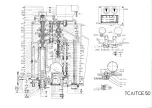
4.  El mando del dispositivo del expulsor automático de la herramienta deberá estar siempre en la posición "A", s/dibujo nº 2 

(página 4). 

5.  No trabajar en avance automático, mientras el mando nº 3, esté en la posición "B", S/dibujo nº 2 y 3 (página 4). 
6.  Se deberá tener siempre en cuenta, tanto trabajando en avance manual como en automático, los posibles golpes que 

pueda ocasionar el mando nº 14 (página 9) debido a la energía elástica del muelle de recuperación del eje principal. 


• 

REPARACIÓN Y MANTENIMIENTO.


Todas las operaciones de reparación y mantenimiento, han de realizarse por personal capacitado y tomando las 
medidas de seguridad pertinentes. 


• 

DEPOSITO DE REFRIGERANTE


La base del taladro se utiliza como depósito de refrigerante, que tiene una capacidad de: 
TCA.50 

13 litros 


IMPORTANT

: Before starting with the installation, you should read this operation handbook carefully. 


STEPS TO FOLLOW 


• 

Machine handling and transport 

• 

Machine start-up. 

• 

Operation and adjustment. 

• 

Most important maintenance and repairs operations. 


DESCRIPTION OF THE ABOVE STEPS 


• 

MACHINE HANDLING AND TRANSPORT.


Machine handling from floor-transport-floor or another transport, is carried out with suitable cranes and lifting auxiliary items, 
which must assure enough loading capacity to lift the load safely. 
This handbook also shows how the handling operations must be performed (see page 17). 


• 

MACHINE START-UP.


The machine should be installed in a place, which is protected against inclement weather. The foundation should have 
enough capacity to support the weight of the machine and it should also be tough enough to support the machine without 
inadmissible deformations, which prevent the correct function of the machine. Besides you should avoid the transmission of 
any vibration to the floor or structure of the place. 
You should provide enough room around the machine to ease the operation, handling of materials, machine maintenance 
and staff safety. 
Before the start up of the machine, please note the following: 

• 

Skilled workers, equipped with the correct clothing and tools should carry out the start-up. 

• 

Make sure that the machine has enough space with or without auxiliary tables to allow and ease the safe, working, and 
maintenance and repair operations. 

• 

Ensure that the machine foundation and vibration proof system is adequate. (page 9). 

• 

Check the supply voltage. 

• 

Make sure that the current to be used is the same as the drilling voltage. 

• 

The main switch nr.1 (page 4) is installed in the electric cabinet, as per drawing nr.3 (page 4). - On machines with three 
phase connection, the connection should be EARTH, RST and if required N (N= Neutral). 

• 

Before checking the turning sense, please make sure that the lever nr.1 (page 4) is in "RELEASED" position. To see that, 
the main spindle has to displace manually by means of the command nr.2, as per drawing nr.3 (page 4). See point 7 and 8. 

• 

When the machine is delivered with the electromagnetic clutch (EMEL), the main switch IG, as well as the connections nr.5 
and the current entry nr.6, are placed in the electrical cabinet nr.4, as per drawing nr.3 (page 4). 

• 

Attention, take special care of testing the main spindle turning sense, before running the tapping system by lead 
screw (Extra equipment). 

Summary of Contents for TCA.50

Page 1: ...otencia motor Machine power Motorleistung Puissance moteur Voltaje Voltage Spannung Voltage Fecha de verificación Verification date Abnahmedatum Date de verification CLIENTE CUSTOMER KUNDE CLIENT NOTA IMPORTANTE IMPORTANT NOTE WITCHIGE HINWEISE AVIS IMPORTANT Para piezas de recambio es necesario señalar It is necessary to state for spare parts Für die entsprechenden Ersatzteile muss folgendes ange...

Page 2: ...la corriente que se va a utilizar coincide con el voltaje del taladro En las máquinas de conexión trifásica se han de conectar los cables a las bornes TIERRA RST y N si necesitara N Neutro Antes de comprobar el sentido de giro asegurarse de que el avance del eje principal está DESEMBRAGADO Para ello el eje principal tiene que desplazarse manualmente mediante el mando nº 2 s dibujo nº 3 página 4 Ve...

Page 3: ... página 4 embragando de forma automática el avance de trabajo Para conseguir los distintos avances utilizaremos el selector de avances nº 13 página 9 Los diferentes avances se indican en la las placas indicadoras Hay tres formas de desembragar el avance automático del eje principal Desembragado manual Pulsando el botón del extremo de cualquiera de los cuatro mandos nº 2 S dibujo nº 3 página 4 Puls...

Page 4: ... another transport is carried out with suitable cranes and lifting auxiliary items which must assure enough loading capacity to lift the load safely This handbook also shows how the handling operations must be performed see page 17 MACHINE START UP The machine should be installed in a place which is protected against inclement weather The foundation should have enough capacity to support the weigh...

Page 5: ...mpletely stopped 6 DRILLING DEPTH To adjust the drilling depth loosen the locking nuts nr 7 page 9 and turn the adjusting command of the depth index nr 23 in one or another direction The indexing arrow nr 14 page 9 will show us in mm or inches the drilling depth Once the regulation is over re tighten the locking nuts nr 7 page 9 7 AUTOMATIC FEED MECHANICAL CLUTCH It is carried out by means of a li...

Page 6: ...d while command nr 3 is in B position as per nr 2 and 3 page 4 Take special care while working in manual or automatic feed with command nr 4 page 9 when it returns due to the elastic energy of the return spring of the main spindle REPAIR AND MAINTENANCE All the repair and maintenance operations must be carried out by skilled staff and taking the necessary safety measures COOLANT TANK The base of t...

Page 7: ...2 page 9 du support colonne et avec la commande de déplacement vertical du support colonne nr 15 page 9 régler la hauteur de la table Bloquer de nouveau les commandes de blocage nr 12 page 9 du support colonne 3 REGLAGE DE L INCLINAISON DU SUPPORT DE LA TABLE Dévisser les trois vis nr 8 page 9 et régler l inclinaison de la table suivant les degrés nécessaires indiqués sur la règle graduée du bras ...

Page 8: ...s dans la position A pendant que la machine travaille Voir dessin nr 2 13 BLOCAGE DU FOURREAU Serrer avec une clef Allen la vis nr 20 page 9 Attention N utiliser ce blocage que pour les opérations de fraisage PANNE LA PLUS FREQUENTE RUPTURE DU RESSORT DE RECUPERATION Enlever le couvercle de protection et extraire le ressort Pour le remplacer placer l extrémité centrale du ressort dans la rainure d...

Page 9: ... sind erforderlich Siehe Seite 9 Die Netzspannung muß den Werten der Maschine entsprechen Ist die Maschine für Drehstrom ausgelegt so sind die Anschlüsse R S T Erde und nötigenfalls N zu verwenden Bevor Sie die Drehrichtung überprüfen müssen Sie sich vergewissern daß der automatische Vorschub und der sensorische Vorschub Teile 13 und 14 Zeichnung 9 abgeschaltet sind Siehe hierzu auch Nummer 7 Verg...

Page 10: ...statur Nr 17 siehe Seite 9 Automatisch auskuppeln hierfür muss ide Bohrtiefe mittels der Pfeilanzeige eingestellt werden siehe Punkt 6 9 LANGSAMER HANDVORSCHUB Stellen Sie den Schalthebel für den Vorschub Nr 13 Seite 9 auf 0 Totpunkt und schalten Sie den automatischen Vorschub durch Bewegen eines Knebels des Vorschubrades Nr 14 Seite 9 zu Nun können Sie durch manuelles Drehen am Vorschubrad langsa...

Page 11: ...EN des automatischen Werkzeugaustreibers muß im Maschinenbetrieb stets voll eingeschoben sein IST DAS SO GEMEINT 5 Der automatische Vorschub läßt sich nich regulieren während er eingeschaltet ist 6 Es muß stets sowohl bei der Arbeit mit automatischem wie mit manuellem Vorschub mit den möglichen Schlägen rechnen die von dem Vorschubrad Teil Nr 14 auf Seite 9 auf Grund der elastischen Kraft der Spin...

Page 12: ...MORDAZA GRIP 2 VICE DRAWING 1 DRAWING 2 DRAWING 3 O K O K I G 2 3 DIBUJO 3 DIBUJO 2 DIBUJO 1 A B 5 6 F2 F1 6 5 4 1 2 3 1 C D TCA TCA EMEL ...

Page 13: ...ERLO 600 270 TCA TCE 50 ENGRASE GREASING GRAISSAGE SCHMIERUNG 1 2 3 4 OIL 5 STOP 5 5 2 2 3 3 1 1 1 3 4 1 1 1 2 ...

Page 14: ...Olwechsel ist järlirfich unter der Voraussetzung del einschichtigen Betriebes Capacidad Capacity Capacité Fassungsvolumen Cabezal Headstock Poupée Kopfstuck TS 32 TS 35 TSA 32 TSA 35 TSE 32 TSE 35 1 l TS 25 TS 30 TSA 25 TSA 30 TF 30 2 75 l TC 25 TC 30 TC 32 TC 35 TCA 60 TCA 70 TCA 60BV TCA 70BV 5 l TCA 25 TCA 30 TCA 32 TCA 35 TF 35 8 l V 40 V 45 TCA 40 TCA 45 TCA 50 TCA 45BV 4 l Caja desplazamient...

Page 15: ...E LA MÁQUINA MACHINE DESCRIPTION BESCHREIBUNG DER MASCHINE DESCRIPTION DE LA MACHINE 22 175 150 M14X2 1 2 2 3 4 5 6 1 2 3 4 7 23 2 5 10 11 1 2 2 3 4 6 7 7 23 23 5 10 11 26 26 26 9 8 12 12 12 12 12 27 20 18 21 17 16 25 13 14 15 15 24 22 19 TCA 50 TCE 50 SG MG SF MF MA SF MF ...

Page 16: ...ablauf für oberen Spindelkopf 12 Blocaje del soporte Blocking of support Blocage support Bedienungspult mit Tiefenskala 13 Placa de pulsadores Push button plate Plaque de poussoirs Bedienengspult 14 Índice de profundidad Depth indicator Indice de profondeur Verstellbare Tiefenskala 15 Mando de desplazamiento del soporte Handle of displacement of support Commande de déplacement du support Kurbel fü...

Page 17: ......

Page 18: ...933 M10x20 Screw DIN 933 M10x20 50 1 36 Eje nº 4 Axle nº 4 70 1 71 Arandela distanciadora rodamientos Bearing spacer washer 153 Anilla elástica E 32 Elastic washer E 32 50 1 37 Engranaje eje nº 4 Axle gear nº 4 70 1 73 Engranaje cónico Conical gear 159 Tubo plástico Ø10x1500 Plastic tube Ø10x1500 50 1 38 Engraneje eje nº 4 Axle gear nº 4 8 Engrasador de 6 EF862 Greaser of 6 EF862 160 Tornillo DIN ...

Page 19: ... Vis DIN 933 M10x20 Sechskantschraube M10x20 50 1 36 Axe nº 4 Welle nº 4 70 1 71 Rondelle distanceur roulement Eingriff Lagerbüchse 153 Anneau elastique E 32 Elastischring E 32 50 1 37 Engrenage axe nº 4 Wellengetrieb nº 4 70 1 73 Engrenage conique Konischer Eingriff 159 Tube de plastique Ø10x1500 Plastikrohr Ø10x1500 50 1 38 Engrenage axe nº 4 Wellengetrieb nº 4 8 Graiseur de 6 EF862 Kugelöler 6 ...

Page 20: ...ecteur de profondeur réglable avec arrêt temporisé et inversion automatique de la rotation 8 Butée du détecteur de récupération réglable avec arrêt temporisé et inversion automatique de la rotation 10 Vis de blocage de sécurité pour filetage Enlever la vis pour le cycle de perçage 11 Levier d enclenchement automatique de l avance de perçage Position débrayée PLAQUE CYCLES DE TRAVAIL A1 Cycle conti...

Page 21: ......

Page 22: ...gelstift Ø7x70 10 Espárrago Allen M8x25 Allen stud M8x25 Goujon Allen M8x25 Allen Bolzen M8x25 11 Tubo flex P G 9 10x14x350 Flexible tube P G 9 10x14x350 Tube flex P G 9 10x14x350 Flex Rohr P G 9 10x14x350 13 Prensaestopa P G 13 Stuffing box P G 13 Presse étoupe P G 13 Einführungspresse P G 13 18 Tornillo DIN 912 M8x30 Screw DIN 912 M8x30 Vis DIN 912 M8x30 Schraube DIN 912 M8x30 19 Pasador cónico ...

Page 23: ......

Page 24: ...g 60 1 93 Manilla del disparo automático Automatic trip end handle Manette automatique de fin de course Handgriff der Selbsauslösung 60 1 94 Muelle disparo automático Automatic trip end spring Ressort fin de course automatique Selbstauslösungsfeder 60 1 111 Porta grifo Faucet holder Porte robinet Griffshalter 60 1 117 Casquillo tope End bush Bague de butée Anschlagsbüchse 70 101 Tuerca de apriete ...

Page 25: ...CKING KAFIGVERPAKKUNG GRUA O CARRETILLA ELEVADORA GRUE OU CHARIOT DE LEVEGE CRANE OR LIFT TRUCK KRAN ODER SCHUBKARPE ELEVATOR GRUA GRUE CRANE KRAN 90 8 0 7 0 6 0 5 0 4 0 3 0 2 0 1 0 GRUA O CARRETILLA ELEVADORA GRUE OU CHARIOT DE LEVEGE CRANE OR LIFT TRUCK KRAN ODER SCHUBKARPE ELEVATOR EMBALAJE MARITIMO EMBALLAGE MARITIME SEAWORTHY PACKING MEERVERPAKKUNG ...

Page 26: ...1850 Kg 1600 Kg 1500 Kg 2300 Kg 1900 Kg 2120 Kg MODELOS 3000 Kg 2560 Kg 750 Kg 1150 Kg 950 Kg 910 Kg 1400 Kg 1155 Kg 680 Kg 870 Kg 775 Kg 1025 Kg 1300 Kg 1160 Kg 1050 Kg 1350 Kg 1200 Kg MODEL T TZ TM TR S SR SG SM C CR TRV TMV 18 MODELL MACHINE S SR 30 C CR 30 TS TSA TSE 32 MASCHINE CAGR PACKING 25 30 32 35 40 45 50 60 KAFIG VERPAKKUNG 70 The shown weights are approximate Die zweckmassig gewichte ...

Reviews: