© 2001 – Ericsson Amplifier Technologies Inc.
22
If the output power is below the limited value during a subsequent attempt, the gain of
the module will be increased until either the limited value is reached, or nominal gain is
restored.
4.7.7
Locking
Mode
(Blinking LOOP LED)
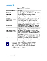
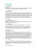
The locking mode is used to indicate that the module is unable to minimize IMD
performance, and is attempting to adjust loop coefficients. During this mode IMD
performance may not meet specified values. The module will attempt to improve
performance for 1 minute. If unable to improve performance during this period, the
module will indicate a loop alarm and enter the shutdown mode.
4.8 Description of Alarm Conditions
The amplifier reports various alarms, indicated via a front panel LED, and via the I/O
connector on the rear. The following paragraphs detail the alarm conditions, and
expected operation during each. Refer also to Table 3 for a description of the alarm
indications.
NOTE
Activation of the LOOP ALARM, VSWR ALARM, POWER
SUPPLY ALARM, TEMP ALARM or OVERPOWER ALARM
will cause the MCPA to shut down. The fault condition may
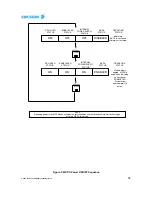
be reset by re-setting power to the MCPA. Refer to Figure 4
for sequence.
4.8.1 LOOP Alarm
Indicates control loops can no longer minimize IMD performance. The sequence of
disable and enable commands may be used to reset the loops to their nominal setting.
4.8.2 VSWR Alarm
When the reverse power is more than 30 Watts for 5 seconds a VSWR is given.
4.8.3 TEMP/WARN Alarm
Two levels of temperature warnings are provided via the dual color TEMP/WARN LED.
A yellow TEMP/WARN LED indicates module heatsink temperature has risen to a high
level, approximately 80 degrees C. . Normal operation can continue, provided the
temperature remains below the 90 degree C TEMP/WARN shutdown level. At
approximately 90 degrees C, the TEMP/WARN indicator will switch to a red color,


